[vc_row][vc_column width=”1/1″][/vc_column][/vc_row][vc_row][vc_column width=”1/1″][vc_column_text]In the following. we begin our first experiment- blinking LED.
The components used in this experiment are shown below.
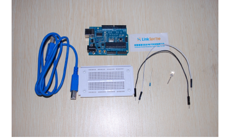
This experiment will need a 470ohm resister,one LED,2 jump wires, and one breadboard.[/vc_column_text][/vc_column][/vc_row][vc_row][vc_column width=”1/1″][vc_tour][vc_tab title=”Schematics” tab_id=”1392604748-1-62″][vc_column_text]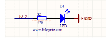
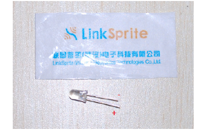
The long pin of LED is positive, and the short pin is negative.[/vc_column_text][/vc_tab][vc_tab title=”Wiring Diagram” tab_id=”1392604748-2-80″][vc_column_text]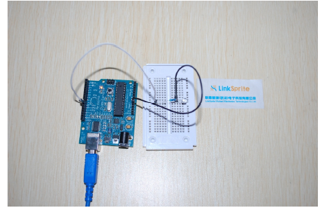
The positive pin of LED is connected to Arduino digital pin 9, and the negative pin of LED is connected to the resistor.The other end of the resistor is connected to GND of Arduino.
[/vc_column_text][/vc_tab][vc_tab title=”Arduino Code” tab_id=”1392606807571-2-6″][vc_column_text]Arduino Code:
int ledPin=9; //Configure the control digital IO pin
void setup()
{
//set the mode of the digital IO pinto be OUTPUT
pinMode(ledPin,OUTPUT);
}
void loop()
{
//Set ledpin to be HIGH, which is equal to 5V
digitalWrite(ledPin,HIGH);
delay(10); //Set the delay time, 2000 is about 2 seconds
//Set ledpin to be LOW, which is equal to 0V
digitalWrite(ledPin,LOW);
delay(350); //Set the delay time, 2000 is about 2 seconds
}[/vc_column_text][/vc_tab][/vc_tour][/vc_column][/vc_row]
Leave a Reply
You must be logged in to post a comment.