[vc_row][vc_column width=”1/1″][vc_column_text]In this experiment,we are going to use a potentiometer to adjust the voltage level of the input signal to an ADC pin so that we can measure the voltage.Please don’t use voltage greater than 5v.
The components used in this experiment are shown below:
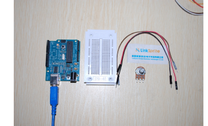
The components are one potentiometer, three jumper wires, and one breadboard.[/vc_column_text][/vc_column][/vc_row][vc_row][vc_column width=”1/1″][vc_tour][vc_tab title=”Schematics” tab_id=”1392619884-1-73″][vc_column_text]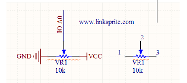
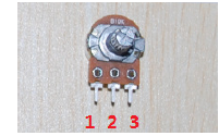
The mapping of the potentiometer pins to the schematics.
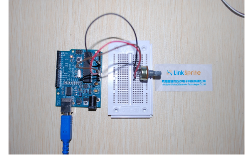
Pin 1 of the potentiometer is connected to GNP,pin 3 is connected to VCC,and pin 2 is connected to AO of the Arduino.[/vc_column_text][/vc_tab][vc_tab title=”Arduino code” tab_id=”1392619884-2-45″][vc_column_text]Arduino code:
void setup()
{
// Open the serial port of Arduino, and set the baud rate to
be9600bps
Serial.begin(9600);
}
void loop()
{
int V;
//The voltage signal is connected to analog port 0
V=analogRead(0);
//send the string to the serial port
Serial.println(V/215.9,DEC);
delay(100);
}[/vc_column_text][/vc_tab][/vc_tour][/vc_column][/vc_row]
Leave a Reply
You must be logged in to post a comment.