[vc_row][vc_column width=”1/1″][vc_column_text]The components used in this experiment are shown below:
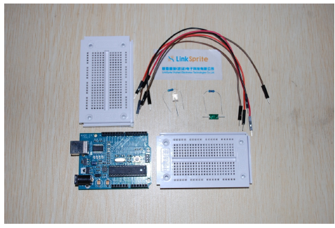
The components are:
- one LED (any color works)
- one 470 ohm resistor
- two 10k ohm resistors
- one rolling ball tilt sensor
- four jumper wires
- and breadboards.
[/vc_column_text][/vc_column][/vc_row][vc_row][vc_column width=”1/1″][vc_tour][vc_tab title=”Schematics” tab_id=”1392622315-1-76″][vc_column_text]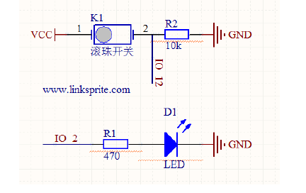 [/vc_column_text][/vc_tab][vc_tab title=”wiring diagram” tab_id=”1392622315-2-60″][vc_column_text]
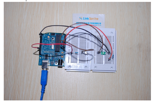
The positive pin of LED is wired to digital pin 12 of Arduino.The output of rolling ball tilt sensor is connected to digital pin 2 of Arduino .Note , please don’t omit the 10k resistor. Otherwise, the power supply will not be stable.[/vc_column_text][/vc_tab][vc_tab title=”Arduino code” tab_id=”1392623142667-2-7″][vc_column_text]Arduino code:
int ledPin = 12; // Define digital pin 12 is used to interface to LED
// Define digital pin 2 is used to interface to tilt sensor
int switch0 = 2;
void setup()
{
pinMode(ledPin, OUTPUT); // Set the mode of digital 12 to be OUTPUT
pinMode(switch0, INPUT); // Set the mode of digital 2 to be INPUT
}
void loop()
{
if(digitalRead(switch0)==HIGH)
{
// Set the digital pin 12 to be HIGH to turn on the LED
digitalWrite(ledPin, HIGH);
}
else
{ // Set the digital pin 12 to be LOW to turn off LED
digitalWrite(ledPin, LOW);
}
}
[/vc_column_text][/vc_tab][/vc_tour][/vc_column][/vc_row]
Leave a Reply
You must be logged in to post a comment.