[vc_row][vc_column width=”1/1″][vc_column_text]This is a handy potentiometer breakout that can be used to adjust signal level in robotics.
There are three pins: power supply, voltage, signal.

[/vc_column_text][vc_tour][vc_tab title=”Parts List” tab_id=”1389204027-1-79″][vc_column_text]1 x Potentiometer Breakout
1 x pcDuino v2
Several Jump Wires[/vc_column_text][/vc_tab][vc_tab title=”Wire Diagram” tab_id=”1389204027-2-72″][vc_column_text]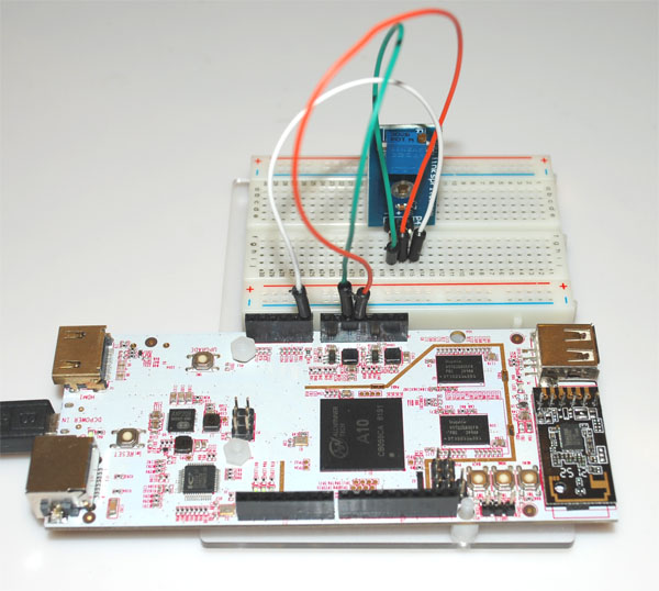
+ of Potentiometer breakout -> 5V of pcDuino
– of Potentiometer breakout -> GND of pcDuino
S of Potentiometer breakout -> A0 of pcDuino
[/vc_column_text][/vc_tab][vc_tab title=”Sample Code” tab_id=”1389204292418-2-4″][vc_column_text]
We use the included Arduino IDE in pcDuino:
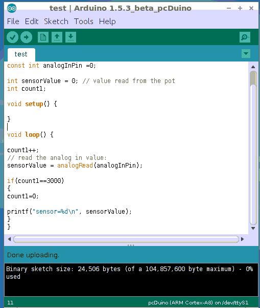
Code:
#include <core.h>
const int analogInPin =0;
int sensorValue = 0; // value read from the pot
int count1;
void setup() {
}
void loop() {
count1++;
// read the analog in value:
sensorValue = analogRead(analogInPin);
if(count1==3000)
{
count1=0;
printf(“sensor=%d\n”, sensorValue);
}
}
[/vc_column_text][/vc_tab][vc_tab title=”Results” tab_id=”1389204315353-3-7″][vc_column_text]
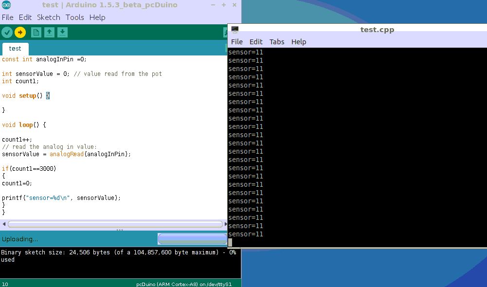
Click the left-point arrow to run the code on pcDuino, the reading changes when we adjust the potentiometer.
[/vc_column_text][/vc_tab][/vc_tour][/vc_column][/vc_row]
Leave a Reply
You must be logged in to post a comment.