[vc_row][vc_column][vc_column_text]Introduction
The ADXL330 is a small, thin, low power, complete three axis accelerometer with signal conditioned voltage outputs, all
on a single monolithic IC. The product measures acceleration with a minimum full-scale range of ±3 g. It can measure the
static acceleration of gravity in tilt-sensing applications, as well as dynamic acceleration resulting from motion, shock, or
vibration.
The user selects the bandwidth of the accelerometer using the CX, CY, and CZ capacitors at the XOUT, YOUT, and ZOUT pins. Bandwidths can be selected to suit the application, with a range of 0.5 Hz to 1,600 Hz for X and Y axes, and a range of
0.5 Hz to 550 Hz for the Z axis. The ADXL330 is available in a small, low-profile, 4 mm × 4 mm × 1.45 mm, 16-lead, plastic lead frame chip scale package (LFCSP_LQ)
 [/vc_column_text][/vc_column][/vc_row][vc_row][vc_column width=”1/1″][vc_tour][vc_tab title=”Parts list” tab_id=”1394002968-1-12″][vc_column_text]Arduino UNO ×1
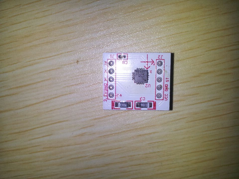
ADXL330K triaxial accelerometer ×1
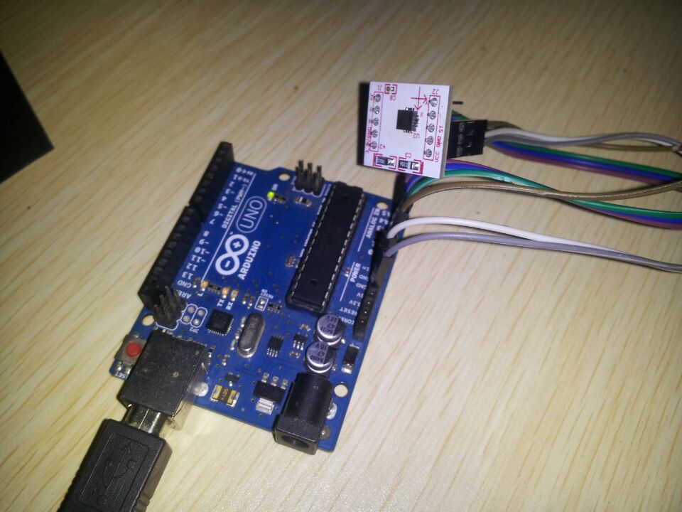
Male to Female Dupont Line× 6[/vc_column_text][/vc_tab][vc_tab title=”Wiring diagram” tab_id=”1394005796210-3-10″][vc_column_text]VCC connect to 5V of Arduino, GND connect to GND of Arduino, ST connect to A0 of Arduino, Z connect to A1 of Arduino, Y connect to A2 of Arduino, X connect to A3 of Arduino
 [/vc_column_text][/vc_tab][vc_tab title=”Test code” tab_id=”1394002968-2-67″][vc_column_text]
/* ADXL3xx The circuit: analog 0: accelerometer self test analog 1: z-axis analog 2: y-axis analog 3: x-axis analog 4: ground analog 5: vcc*/// these constants describe the pins. They won't change:const int groundpin = 18; // analog input pin 4 -- groundconst int powerpin = 19; // analog input pin 5 -- voltageconst int xpin = A3; // x-axis of the accelerometerconst int ypin = A2; // y-axisconst int zpin = A1; // z-axis (only on 3-axis models)void setup(){ // initialize the serial communications: Serial.begin(9600); // Provide ground and power by using the analog inputs as normal // digital pins. This makes it possible to directly connect the // breakout board to the Arduino. If you use the normal 5V and // GND pins on the Arduino, you can remove these lines. pinMode(groundpin, OUTPUT); pinMode(powerpin, OUTPUT); digitalWrite(groundpin, LOW); digitalWrite(powerpin, HIGH);}void loop(){ // print the sensor values: Serial.print(analogRead(xpin)); // print a tab between values: Serial.print("\t"); Serial.print(analogRead(ypin)); // print a tab between values: Serial.print("\t"); Serial.print(analogRead(zpin)); Serial.println(); // delay before next reading: delay(100);}[/vc_column_text][/vc_tab][vc_tab title=”The results” tab_id=”1394003260838-2-9″][vc_column_text]Writing the code to open the serial port , you can see:

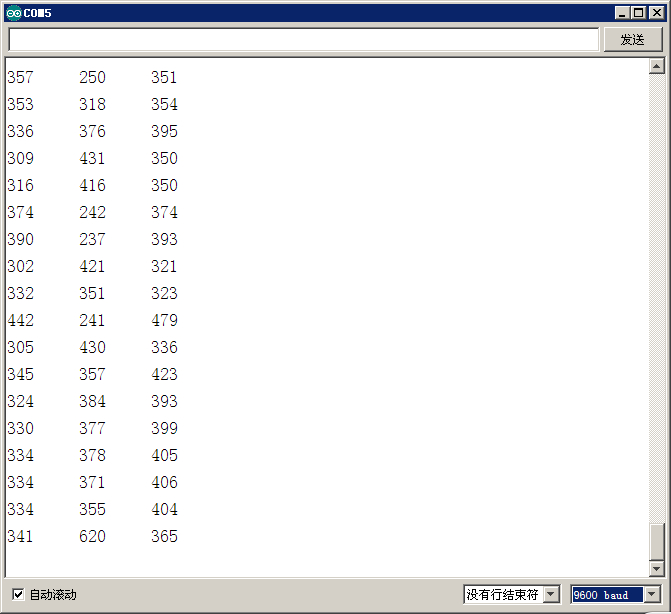
Shake ADXL330 sensor, you can see the data is changing[/vc_column_text][/vc_tab][/vc_tour][/vc_column][/vc_row]
Leave a Reply
You must be logged in to post a comment.