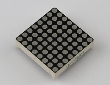
[vc_row][vc_column width=”1/1″][vc_column_text]This experiment uses a dual color LED matrix, which is a red and green color 8 × 8 matrix, the physical pin diagram of matrix is given below. This experiment only drives the red only.
 [/vc_column_text][/vc_column][/vc_row][vc_row][vc_column width=”1/1″][vc_tour][vc_tab title=”Parts List” tab_id=”1389060412-1-38″][vc_column_text]
- 1 x pcDuino experiment platform
- 1 x dual color 8×8 LED matrix
- Several jumper wires
[/vc_column_text][/vc_tab][vc_tab title=”Wiring” tab_id=”1389060412-2-74″][vc_column_text]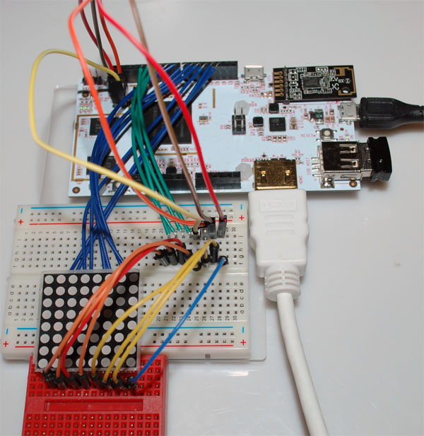
| UNO pin | matrix pin (red pin as an example) | |
|---|---|---|
| 2 | 23 | |
| 3 | 22 | |
| 4 | 20 | |
| 5 | 19 | |
| 6 | 17 | |
| 7 | 16 | |
| 8 | 14 | |
| 9 | 13 | |
| 10 | 2 | |
| 11 | 3 | |
| 12 | 5 | |
| 13 | 6 | |
| 14 | 8 | |
| 15 | 9 | |
| 16 | 11 | |
| 17 | 12 |
[/vc_column_text][/vc_tab][vc_tab title=”Test Code” tab_id=”1389061348583-2-4″][vc_column_text]
The entire code can be(ledmatrix) download here.
Code as follows:
/* * Show messages on an 8x8 led matrix, * scrolling from right to left. * * Uses FrequencyTimer2 library to * constantly run an interrupt routine * at a specified frequency. This * refreshes the display without the * main loop having to do anything. * */ #include <core.h> #define SPACE { \ {0, 0, 0, 0, 0, 0, 0, 0}, \ {0, 0, 0, 0, 0, 0, 0, 0}, \ {0, 0, 0, 0, 0, 0, 0, 0}, \ {0, 0, 0, 0, 0, 0, 0, 0}, \ {0, 0, 0, 0, 0, 0, 0, 0}, \ {0, 0, 0, 0, 0, 0, 0, 0}, \ {0, 0, 0, 0, 0, 0, 0, 0}, \ {0, 0, 0, 0, 0, 0, 0, 0} \ } #define H { \ {0, 1, 0, 0, 0, 0, 1, 0}, \ {0, 1, 0, 0, 0, 0, 1, 0}, \ {0, 1, 0, 0, 0, 0, 1, 0}, \ {0, 1, 1, 1, 1, 1, 1, 0}, \ {0, 1, 0, 0, 0, 0, 1, 0}, \ {0, 1, 0, 0, 0, 0, 1, 0}, \ {0, 1, 0, 0, 0, 0, 1, 0}, \ {0, 1, 0, 0, 0, 0, 1, 0} \ } #define E { \ {0, 1, 1, 1, 1, 1, 1, 0}, \ {0, 1, 0, 0, 0, 0, 0, 0}, \ {0, 1, 0, 0, 0, 0, 0, 0}, \ {0, 1, 1, 1, 1, 1, 1, 0}, \ {0, 1, 0, 0, 0, 0, 0, 0}, \ {0, 1, 0, 0, 0, 0, 0, 0}, \ {0, 1, 0, 0, 0, 0, 0, 0}, \ {0, 1, 1, 1, 1, 1, 1, 0} \ } #define L { \ {0, 1, 0, 0, 0, 0, 0, 0}, \ {0, 1, 0, 0, 0, 0, 0, 0}, \ {0, 1, 0, 0, 0, 0, 0, 0}, \ {0, 1, 0, 0, 0, 0, 0, 0}, \ {0, 1, 0, 0, 0, 0, 0, 0}, \ {0, 1, 0, 0, 0, 0, 0, 0}, \ {0, 1, 0, 0, 0, 0, 0, 0}, \ {0, 1, 1, 1, 1, 1, 1, 0} \ } #define O { \ {0, 0, 0, 1, 1, 0, 0, 0}, \ {0, 0, 1, 0, 0, 1, 0, 0}, \ {0, 1, 0, 0, 0, 0, 1, 0}, \ {0, 1, 0, 0, 0, 0, 1, 0}, \ {0, 1, 0, 0, 0, 0, 1, 0}, \ {0, 1, 0, 0, 0, 0, 1, 0}, \ {0, 0, 1, 0, 0, 1, 0, 0}, \ {0, 0, 0, 1, 1, 0, 0, 0} \ } byte col = 0; byte leds[8][8]; // pin[xx] on led matrix connected to nn on Arduino (-1 is dummy to make array start at pos 1) int pins[17]= {17,15,13,11,9,7,5,3,2,4,6,8,10,12,14,16};; // col[xx] of leds = pin yy on led matrix int cols[8] = {pins[0], pins[1], pins[2], pins[3], pins[4], pins[5], pins[6], pins[7]}; // row[xx] of leds = pin yy on led matrix int rows[8] = {pins[8], pins[9], pins[10], pins[11], pins[12], pins[13], pins[14], pins[15]}; const int numPatterns = 6; byte patterns[numPatterns][8][8] = { H,E,L,L,O,SPACE }; int pattern = 0; void setup() { // sets the pins as output for (int i = 0; i < 16; i++) { pinMode(pins[i], OUTPUT); } // set up cols and rows for (int i = 1; i <= 8; i++) { digitalWrite(cols[i - 1], LOW); } for (int i = 1; i <= 8; i++) { digitalWrite(rows[i - 1], LOW); } clearLeds(); setPattern(pattern); } void loop() { pattern = 3; setPattern(pattern); display(); } void clearLeds() { // Clear display array for (int i = 0; i < 8; i++) { for (int j = 0; j < 8; j++) { leds[i][j] = 0; } } } void setPattern(int pattern) { for (int i = 0; i < 8; i++) { for (int j = 0; j < 8; j++) { leds[i][j] = patterns[pattern][i][j]; } } } void slidePattern(int pattern, int del) { for (int l = 0; l < 8; l++) { for (int i = 0; i < 7; i++) { for (int j = 0; j < 8; j++) { leds[j][i] = leds[j][i+1]; } } for (int j = 0; j < 8; j++) { leds[j][7] = patterns[pattern][j][0 + l]; } delay(del); } } // Interrupt routine void display() { digitalWrite(cols[col], LOW); // Turn whole previous column off col++; if (col == 8) { col = 0; } for (int row = 0; row < 8; row++) { if (leds[7-col][row] == 1) { digitalWrite(rows[row], LOW); // Turn on this led } else { digitalWrite(rows[row], HIGH); // Turn off this led } } digitalWrite(cols[col], HIGH); // Turn whole column on at once (for equal lighting times) |
[/vc_column_text][/vc_tab][vc_tab title=”Results” tab_id=”1389061591574-3-1″][vc_column_text] [/vc_column_text][/vc_tab][/vc_tour][/vc_column][/vc_row]
Leave a Reply
You must be logged in to post a comment.