I2C Tools :
This page documents I2C tools i2cdetect, i2cdump, i2cget and i2cset.
These tools can be invaluable for hardware monitoring device identification and troubleshooting.
| I2C bus | ||
| Bus scanning | i2cdetect | |
| Device register dumping | i2cdump | |
| Device register reading | i2cget | |
| Device register setting | i2cset |
All i2c tools operate on a specific i2c bus which is identified by number. The applicable i2c bus driver must be installed first. The bus numbers are assigned in the order the i2c bus drivers are installed.
The i2c bus number assignments can be listed by i2cdetect -l.
Using I2C tools for device identification
This is a small step-by-step example that is intended to give you an idea on how these tools can be used. Before you go on, please note that it is possible to break your hardware with these tools. Therefore you should be very careful when using them, you should know what you are doing and why you are doing it. If you don’t really know what you are doing and you can’t afford losing part of your hardware, please stop now.
Install i2c-tools on pcDuino Ubuntu
$ sudo apt-get install i2c-tools
Step 1: Identify the I2C buses
Here is an example of using i2cdetect to query an i2c bus.
root@ubuntu:~# i2cdetect -l
i2c-0   i2c          sunxi-i2c.0                        I2C adapter
i2c-1   i2c          sunxi-i2c.1                        I2C adapter
i2c-2   i2c          sunxi-i2c.2                        I2C adapter
i2c-10  i2c          sunxi-hdmi-i2c                     I2C adapter
See also: i2cdetect
Step 2: Query the I2C bus
It is apparent that pcDuino 3. Use the bus number 0 as the argument to i2cdetect:
WARNING: groups:can not find name for group ID 0 when restart pcDuino after run” i2cdetect 0″.
WARNING! This program can confuse your I2C bus, cause data loss and worse!
Tips: 0 = number zero ( not alphabet O)
root@ubuntu:~# i2cdetect 0
WARNING! This program can confuse your I2C bus, cause data loss and worse!
I will probe file /dev/i2c-0.
I will probe address range 0x03-0x77.
Continue? [Y/n] y
     0  1  2  3  4  5  6  7  8  9  a  b  c  d  e  f
00:          -- -- -- -- -- -- -- -- -- -- -- -- --
10: -- -- -- -- -- -- -- -- -- -- -- -- -- -- -- --
20: -- -- -- -- -- -- -- -- -- -- -- -- -- -- -- --
30: -- -- -- -- UU -- -- -- -- -- -- -- -- -- -- --
40: -- -- -- -- -- -- -- -- -- -- -- -- -- -- -- --
50: -- -- -- -- -- -- -- -- -- -- -- -- -- -- -- --
60: -- -- -- -- -- -- -- -- -- -- -- -- -- -- -- --
70: -- -- -- -- -- -- -- --
root@ubuntu:~#
It is apparent that bus 0 is the motherboard’s SMBus. Use the bus number 0 as the argument to i2cdetect:
# i2cdetect 0
WARNING! This program can confuse your I2C bus, cause data loss and worse!
I will probe file /dev/i2c-0.
I will probe address range 0x03-0x77.
Continue? [Y/n]
     0  1  2  3  4  5  6  7  8  9  a  b  c  d  e  f
00:          -- -- -- -- -- -- -- -- -- -- -- -- --
10: -- -- -- -- -- -- -- -- -- -- -- -- -- -- -- --
20: -- -- -- -- -- -- -- -- -- -- -- -- -- 2d -- --
30: -- -- -- -- -- -- -- -- -- -- -- -- -- -- -- --
40: -- -- -- -- -- -- -- -- 32 33 -- -- -- -- -- --
50: 34 35 36 -- -- -- -- -- -- -- -- -- -- -- -- --
60: -- -- -- -- -- -- -- -- -- 59 -- -- -- -- -- --
70: -- -- -- -- -- -- -- --
Step 3: Identify the likely sensors device
The i2cdetect output above shows devices at addresses 0x2d, 0x32, 0x33, 0x34-36, and 0x59.
From consulting the chart below we can attempt to figure out what chips are likely to be sensors. I2C devices generally appear at standard bus addresses as shown below. This chart may prove helpful in device identification. Beware that this is only a hint though, virtually any type of device can live at any I2C address.
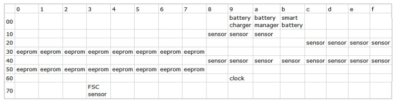
So, back to our example above: the devices at 0x2d, 0x32, and 0x33 are probably sensors (actually a single Winbond hardware monitoring chip responding at three addresses). The devices at 0x34 – 0x36 are most certainly EEPROMs on the three SDRAM DIMMs installed on the motherboard. And the device at 0x59 would be a clock chip.
Step 4: Dump the I2C device registers
Here is an example of using i2cdump to view the registers of an i2c device. This is useful to developers debugging the driver for the device. Warning: it is strongly advised that you do not run i2cdump on a device unless you have a preliminary idea of what this device could be. If you are looking for a sensor chip, you only want to try the addresses in the ranges 0x18-0x1a, 0x2c-0x2f and 0x48-0x4f, as documented in the chart above (and, for Fujitsu-Siemens computers, 0x73). Other addresses are very unlikely to be sensor chips, and attempting to dump them could harm your system.
Use the bus number as the first argument and the chip address as the second argument:
# i2cdump 0 0x2d
No size specified (using byte-data access)
WARNING! This program can confuse your I2C bus, cause data loss and worse!
I will probe file /dev/i2c-0, address 0x2d, mode byte
Continue? [Y/n]
     0  1  2  3  4  5  6  7  8  9  a  b  c  d  e  f
00: ff ff ff ff ff ff ff ff ff ff ff ff ff ff ff ff
10: ff ff ff ff ff ff ff ff ff ff ff ff ff ff ff ff
20: 8a 8b de bb c9 d8 d0 1d ff ff aa c1 9e c1 9e e3
30: ba cc a8 d8 b2 ed c2 e4 bb 3c 32 e1 e1 e1 00 00
40: 01 c3 00 00 00 00 40 50 2d 01 01 40 01 95 00 a3
50: 10 01 80 ff ff ff 00 00 11 ff ff ff ff ff ff ff
60: 8a 8b de bb c9 d6 d1 1d ff ff aa c1 9e c1 9e e3
70: ba cc a8 d8 b2 ed c2 e4 bb 3c 32 e1 e1 e1 00 00
80: ff ff ff ff ff ff ff ff ff ff ff ff ff ff ff ff
90: ff ff ff ff ff ff ff ff ff ff ff ff ff ff ff ff
a0: 8b 8b de bb c8 d9 d1 1d ff ff ab c1 9e c1 9e e3
b0: ba cc a8 d8 b2 ed c2 e4 bb 3c 32 e1 e1 e1 00 00
c0: 01 c3 00 00 00 00 40 50 2d 01 01 40 01 95 00 a3
d0: 10 01 80 ff ff ff 00 00 11 ff ff ff ff ff ff ff
e0: 8a 8a de bb c9 d8 d1 1d ff ff aa c1 9e c1 9e e3
f0: ba cc a8 d8 b2 ed c2 e4 bb 3c 32 e1 e1 e1 00 00
See also: i2cdump
i2cget and i2cset
For advanced debugging you can use the i2cget and i2cset commands to read from, respectively write to, an I2C device. As for i2cdump, you should be very careful when using these commands, if you don’t know what you’re doing, chances are that you’ll break something. The general usage is:
i2cget <bus> <chip> <register>
i2cset <bus> <chip> <register> <value>
For example, the following writes the value 0x22 to register 0x10 of device 0x2d on i2c bus 0:
# i2cset 0 0x2d 0x10 0x22
Leave a Reply
You must be logged in to post a comment.