[vc_row][vc_column][vc_column_text]Breathing Light introduction:
Breathing light is a status light really, also used for notification if a new message arrives or perhaps if you missed a phone call. you might want to consider turning it off if you are concerned with battery life as it does use a bit more, tho i am not sure if it is that significant.
PWM:Pulse Width Modulation
A digital device like a microcontroller can easily work with inputs and outputs that has only two state, on and off. So you can easily use it to control a LED’s state i.e. on or off. In the same way you can use it to control any electrical device on/off by using proper drivers (transistor,triac, relays etc). But sometimes you need more than just “on” & “off ” control over the device. Like if you wanna control the brightness of a LED (or any lamp) or the speed of DC motor then digital (on/off) signals simply can’t do it. This situation is very smartly handled by a technique called PWM or Pulse Width Modulation.
A digital device, like a microcontroller can only generate two levels on its output lines, HIGH=5v and LOW=0V. But what if we want to generate 2.5v or 3.1v or any voltage between 0-5 volt output ? For these kinds of requirement, instead of generating a constant DC voltage output we generate a square wave, which has high = 5V and Low = 0v (See figure 1).
PWM on pcDuino:
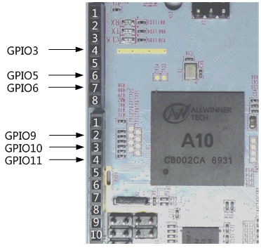
pcDuino have a total of six GPIO can be used output PWM signal, which is defined as shown below. GPIO3, 9,10,11 PWM frequency range of 125Hz ~ 2KHz, GPIO5, 6 PWM frequency range can only be set to 195Hz, 260Hz, 390Hz, 520Hz, 781Hz in a particular value. Arduino library provides analogWrite () function to set the PWM duty cycle, also increase pwmfreq_set () function, can set the PWM signal period.[/vc_column_text][/vc_column][/vc_row][vc_row][vc_column width=”1/1″][vc_tour][vc_tab title=”Parts List” tab_id=”1395047096-1-61″][vc_column_text]
- pcDuinoV2 x1
- 5mmLED x1
- 560 ohm resistor color ring x1
- Breadboard x1
- Several jump wires
[/vc_column_text][/vc_tab][vc_tab title=”Wiring Diagram” tab_id=”1395047096-2-34″][vc_column_text]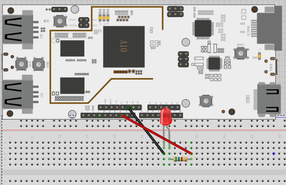 [/vc_column_text][/vc_tab][vc_tab title=”Test Code” tab_id=”1395049275767-2-5″][vc_column_text]
#include <core.h>

// Macro definitions and global variables
#define LED_MAX_PWM   0x25  //LED highest brightness corresponding PWM parameters
#define DELAY_TIME    50  //The duration of each brightness value

int ledPin=10; //LED connect to GPIO10

// Initialize the settings section
void setup()
{
  pinMode(ledPin, OUTPUT);
}

//Loop operative
void loop()
{
 int i;
  //Gradually increase the brightness
  for(i=0;i<=LED_MAX_PWM;i++)
  {
    analogWrite(ledPin, i); //设置PWM占空比
    delay(DelayTime);
  }

  //The brightness gradually decay
  for(i=LED_MAX_PWM;i>=0;i--)
  {
    analogWrite(ledPin, i);
    delay(DelayTime);
  }
}
[/vc_column_text][/vc_tab][/vc_tour][/vc_column][/vc_row]
Leave a Reply
You must be logged in to post a comment.