[vc_row][vc_column][vc_column_text]This project shows how to code a bare metal program for pcDuino.
Development Environment:
System: ubuntu 10.04.4
Hardware: pcDuino
Compiler: arm-2009q3-67-arm-none-linux-gnueabi-i686-pc-linux-gnu.tar.bz2
Objective: To blink TX_LED of pcDuino.
First, hardware description
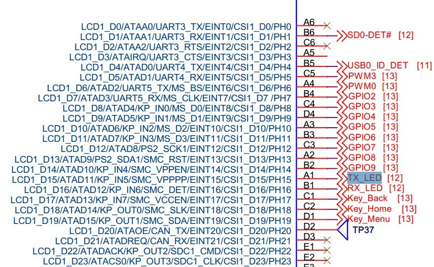
Look carefully at the schematic of pcDuino and pcDuino manual. According to the schematic ,TX_LED is connected to PH15, can be used as general IO port.
Second, write LED led initialization it includes files start.S, main.c, clock.c, clock.h, Makefile and all the following code:
File start.S:
view plaincopyprint?.global _start
_start:
ldr sp, =0x00007f00
b main
.global _start
_start:
ldr sp, =0x00007f00
b main
file main.c:
view plaincopyprint?#include “clock.h”
#define PH_CFG1 (*(volatile unsigned int *)0x01c20900)
#define PH_DAT (*(volatile unsigned int *)0x01c2090C)
#define PH_DRI (*(volatile unsigned int *)0x01c20910)
#define PH_PULL (*(volatile unsigned int *)0x01c20918)
void gpio_init()
{
/*PCDUINO GPIO4–PH9:
*bit[6:4] PH9_SELECT 001:OUTPUT
*PCDUINO GPIO5–PH10:
*bit[10:8] PH10_SELECT 001:OUTPUT
*/
PH_CFG1 |= ((0×1<<4)|(0×1<<8)|(0X1<<28));
PH_DRI = 0XFFFFFFFF;
PH_PULL = 0X55555555;
}
void delay()
{
volatile int i = 0×300000;
while (i–);
}
int main(void)
{
char c;
clock_init(); /* Initialize the clock */
gpio_init();
while (1)
{
PH_DAT = 0×00;
delay();
PH_DAT = 0xffff;
delay();
}
return 0;
}
#include “clock.h”
#define PH_CFG1 (*(volatile unsigned int *)0x01c20900)
#define PH_DAT (*(volatile unsigned int *)0x01c2090C)
#define PH_DRI (*(volatile unsigned int *)0x01c20910)
#define PH_PULL (*(volatile unsigned int *)0x01c20918)
void gpio_init()
{
/*PCDUINO GPIO4–PH9:
*bit[6:4] PH9_SELECT 001:OUTPUT
*PCDUINO GPIO5–PH10:
*bit[10:8] PH10_SELECT 001:OUTPUT
*/
PH_CFG1 |= ((0×1<<4)|(0×1<<8)|(0X1<<28));
PH_DRI = 0XFFFFFFFF;
PH_PULL = 0X55555555;
}
void delay()
{
volatile int i = 0×300000;
while (i–);
}
int main(void)
{
char c;
clock_init(); /*Initialize the clock*/
gpio_init();
while (1)
{
PH_DAT = 0×00;
delay();
PH_DAT = 0xffff;
delay();
}
return 0;
}
file clock.c:
view plaincopyprint?#define CPU_AHB_APB0_CFG (*(volatile unsigned int *)0x01c20054)
#define PLL1_CFG (*(volatile unsigned int *)0x01c20000)
#define APB1_CLK_DIV_CFG (*(volatile unsigned int *)0x01c20058)
#define APB1_GATE (*(volatile unsigned int *)0x01c2006C)
void sdelay(unsigned long loops)
{
__asm__ volatile(“1:\n” “subs %0, %1, #1\n”
“bne 1b”:”=r” (loops):”0″(loops));
}
void clock_init(void)
{
/*AXI_DIV_1[1:0] AXI_CLK_DIV_RATIO 00:/1 AXI Clock source is CPU clock
*AHB_DIV_2[5:4] AHP_CLK_DIV_RATIO 01:/2 AHB Clock source is AXI CLOCK
*APB0_DIV_1[9:8] APB0_CLK_RATIO 00:/2 APB0 clock source is AHB2 clock
*CPU_CLK_SRC_OSC24M[17:16] CPU_CLK_SRC_SEL 01:OSC24M
*/
CPU_AHB_APB0_CFG = ((0<<0)|(0×1<<4)|(0<<8)|(1<<16));
/*bit31 PLL1_Enable 1:Enable
*bit25:EXG_MODE 0×0:Exchange mode
*bit[17:16] PLL1_OUT_EXT_DIVP 0x0P=1
*bit[12:8]PLL1_FACTOR_N 0×10:Factor=16,N=16
*bit[5:4] PLL1_FACTOR_K 0×0:K=1
*bit3:SIG_DELT_PAT_IN 0×0
*bit2:SIG_DELT_PAT_EN 0×0
*bit[1:0]PLL1_FACTOR_M 0×0:M=1
*The PLL1 output=(24M*N*K)/(M*P)=(24M*16*1)/(1*1)=384M is for the coreclk
*/
PLL1_CFG = 0xa1005000;
sdelay(200);
CPU_AHB_APB0_CFG = ((0<<0)|(0×1<<4)|(0<<8)|(2<<16));//CPU_CLK_SRC_SEL 10PLL1
/*uart clock source is apb1,config apb1 clock*/
/*bit[25:24]:APB1_CLK_SRC_SEL 00:OSC24M
*bit[17:16]:CLK_RAT_N 0X0:1 The select clock source is pre-divided by 2^1
*bit[4:0]:CLK_RAT_M 0×0:1 The pre-devided clock is divided by(m+1)
*/
APB1_CLK_DIV_CFG = ((0<<5)|(0<<16)|(0<<24));
/*open the clock for uart0*/
/*bit16:UART0_APB_GATING 1:pass 0:mask*/
APB1_GATE = (0×1<<16);
}
#define CPU_AHB_APB0_CFG (*(volatile unsigned int *)0x01c20054)
#define PLL1_CFG (*(volatile unsigned int *)0x01c20000)
#define APB1_CLK_DIV_CFG (*(volatile unsigned int *)0x01c20058)
#define APB1_GATE (*(volatile unsigned int *)0x01c2006C)
void sdelay(unsigned long loops)
{
__asm__ volatile(“1:\n” “subs %0, %1, #1\n”
“bne 1b”:”=r” (loops):”0″(loops));
}
void clock_init(void)
{
/*AXI_DIV_1[1:0] AXI_CLK_DIV_RATIO 00:/1 AXI Clock source is CPU clock
*AHB_DIV_2[5:4] AHP_CLK_DIV_RATIO 01:/2 AHB Clock source is AXI CLOCK
*APB0_DIV_1[9:8] APB0_CLK_RATIO 00:/2 APB0 clock source is AHB2 clock
*CPU_CLK_SRC_OSC24M[17:16] CPU_CLK_SRC_SEL 01:OSC24M
*/
CPU_AHB_APB0_CFG = ((0<<0)|(0×1<<4)|(0<<8)|(1<<16));
/*bit31 PLL1_Enable 1:Enable
*bit25:EXG_MODE 0×0:Exchange mode
*bit[17:16]PLL1_OUT_EXT_DIVP 0×0 P=1
*bit[12:8]PLL1_FACTOR_N 0×10:Factor=16,N=16
*bit[5:4]PLL1_FACTOR_K 0×0:K=1
*bit3:SIG_DELT_PAT_IN 0×0
*bit2:SIG_DELT_PAT_EN 0×0
*bit[1:0]PLL1_FACTOR_M 0×0:M=1
*The PLL1 output=(24M*N*K)/(M*P)=(24M*16*1)/(1*1)=384M is for the coreclk
*/
PLL1_CFG = 0xa1005000;
sdelay(200);
CPU_AHB_APB0_CFG = ((0<<0)|(0×1<<4)|(0<<8)|(2<<16));//CPU_CLK_SRC_SEL 10PLL1
/*uart clock source is apb1,config apb1 clock*/
/*bit[25:24]:APB1_CLK_SRC_SEL 00:OSC24M
*bit[17:16]:CLK_RAT_N 0X0:1 The select clock source is pre-divided by 2^1
*bit[4:0]:CLK_RAT_M 0×0:1 The pre-devided clock is divided by(m+1)
*/
APB1_CLK_DIV_CFG = ((0<<5)|(0<<16)|(0<<24));
/*open the clock for uart0*/
/*bit16:UART0_APB_GATING 1 pass 0:mask*/
APB1_GATE = (0×1<<16);
}
file·clock.h:
view plaincopyprint?void clock_init(void);
void clock_init(void);文件·Makefile:
view plaincopyprint?led.bin:start.S main.c clock.c
arm-none-linux-gnueabi-gcc -nostdlib -c start.S -o start.o
arm-none-linux-gnueabi-gcc -nostdlib -c main.c -o main.o
arm-none-linux-gnueabi-gcc -nostdlib -c clock.c -o clock.o
arm-none-linux-gnueabi-ld -Ttext 0xD0020010 start.o main.o clock.o -o led_elf
arm-none-linux-gnueabi-objcopy -O binary -S led_elf led.bin
clean:
rm -rf *.o *.bin led_elf *.dis
led.bin:start.S main.c clock.c
arm-none-linux-gnueabi-gcc -nostdlib -c start.S -o start.o
arm-none-linux-gnueabi-gcc -nostdlib -c main.c -o main.o
arm-none-linux-gnueabi-gcc -nostdlib -c clock.c -o clock.o
arm-none-linux-gnueabi-ld -Ttext 0xD0020010 start.o main.o clock.o -o led_elf
arm-none-linux-gnueabi-objcopy -O binary -S led_elf led.bin
clean:
rm -rf *.o *.bin led_elf *.dis
Third, compile and test
1.Install the cross compiler chain, click link http://code.google.com/p/smp-on-qemu/downloads/list”> http://code.google.com/p/smp-on-qemu/downloads/list choose arm-2009q3-67-arm-none-linux-gnueabi-i686-pc- linux-gnu.tar.bz2 and download. Then extract it under ubuntu.If you do not know, you can refer to the Ubuntu 10.04.4 development environment configuration.
2. Compile
change@change:~$ cd Si/A10/2_led/
change@change:~/Si/A10/2_led$ ls
clock.c  clock.h  main.c  Makefile  mksunxiboot  start.S
change@change:~/Si/A10/2_led$ make
arm-none-linux-gnueabi-gcc -nostdlib -c start.S -o start.o
arm-none-linux-gnueabi-gcc -nostdlib -c main.c -o main.o
arm-none-linux-gnueabi-gcc -nostdlib -c clock.c -o clock.o
arm-none-linux-gnueabi-ld -Ttext 0xD0020010 start.o main.o clock.o  -o led_elf
arm-none-linux-gnueabi-objcopy -O binary -S led_elf led.bin
change@change:~/Si/A10/2_led$ ./mksunxiboot led.bin leds.bin
File size: 0×154
Load size: 0×154
Read 0×154 bytes
Write 0×200 bytes
change@change:~/Si/A10/2_led$
3.Test
Above the generated leds.bin can running on the board. In order not to break the system of NAND, directly put into the TF Card to operate. Don’t worry about the start, look at the allwinner allwinner manual, we can know pcDuino default to boot from the TF card. It will only boot from NAND if it failed to boot from SD card.
change@change:~/Si/A10/2_led$ sudo dd if=/dev/zero of=/dev/sdb bs=1M count=1
1+0 records in
1+0 records out
1048576 bytes (1.0 MB) copied, 0.425886 s, 2.5 MB/s
change@change:~/Si/A10/2_led$ sudo dd if=leds.bin of=/dev/sdb bs=1024 seek=8
0+1 records in
0+1 records out
512 bytes (512 B) copied, 0.00600667 s, 85.2 kB/s
change@change:~/Si/A10/2_led$
Then remove the TF card ,insert into the pcDuino, and reboot. RX, LED begin to blink. If you have leds connected to GPIO4, GPIO5, they will also blink.[/vc_column_text][/vc_column][/vc_row]
Leave a Reply
You must be logged in to post a comment.