[vc_row][vc_column][vc_tta_tour][vc_tta_section title=”Introduction” tab_id=”1462952136361-8a2f66b4-7f5c”][vc_column_text]Increasingly you may need to connect to your Arduino devices that operate with 3.3V.
Lowering the integrated circuits’ operating voltage has in fact several advantages:
- allows to realize smaller transistors
- requires a lower heat dissipation
- allows faster state changes (the voltage difference between a logic state LOW and HIGH is lower)
this is why manufacturers of modules, sensors … are adopting the voltage of 3.3V as the standard.
[/vc_column_text][/vc_tta_section][vc_tta_section title=”The problem” tab_id=”1462953647996-a78ab9a3-8421″][vc_column_text][/vc_column_text][vc_column_text]
The problem
Take as a reference an Arduino Uno. The board can be powered in different ways (through the 2.1mm jack, via the USB connector…) but the operation voltage is 5V, supplied by the onboard regulator:
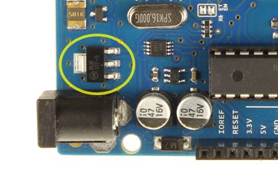
The board has also a 3.3V regulator (LP2985), you may use to power external devices with that voltage:
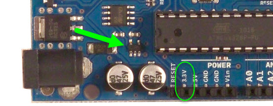
All the PINs therefore works at 5V: if a digital PIN is configured as output, a logical value 1 (digitalWrite(PIN, HIGH);) corresponds to a voltage of 5V on that PIN.
If instead the PIN is configured as input, a voltage greater than 2.5V on that PIN will be considered as a logical value 1; a voltage lower than 2.5V as a logical value 0.
Let’s now connect to that PIN a corresponding PIN of a device powered at 3.3V:
- if the Arduino PIN is configured as input (device -> Arduino) there are no problems: when the device wants to send a logic high, it imposes a voltage of 3.3V that is correctly interpreted by Arduino (> 2.5V);
- if instead the Arduino PIN si configured as output (Arduino -> device), in case of a logic high Arduino imposes a voltage of 5V, that exceeds the working voltage of the device and can thus damage it!
[/vc_column_text][/vc_tta_section][vc_tta_section title=”Solutions” tab_id=”1463019426696-62cad387-e92f”][vc_column_text]
Solutions
There are several possible solutions to adapt the two operating voltages.
The simplest ones, require only passive components (diodes, resistors…). Le soluzioni più semplici utilizzano soltanto componenti passivi (diodi, resistenze…). These solutions work well from the point of view of the tensions but introduce transients during the transitions of state that do not make them suitable for high-speed communications. Some of these solutions are well described in this blog post and their effects are shown on an oscilloscope.
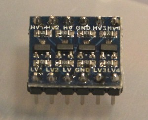
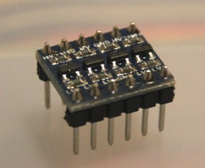
The solution I adopted and suggest uses a small module, sold by several webshops (for example I got mine from Banggood):
This module uses transistors to convert up to 4 signals.
Its use is very simple: first to connect the to HV the higher supply voltage and to LV the lower; then connect the ground (GND). Connect the PINs of the device with higher voltage to the PINs labeled as HVx, while the corresponding PINs of the other device to the PINs labeled as LVx.
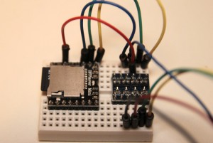
For example, to make a serial connection between Arduino and a device working ad 3.3V, the connections are as follows:
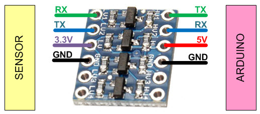
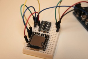
Here’s an example of the use of the module on a breadboard:
For more details,please refer to original post
http://www.lucadentella.it/en/2015/09/12/collegare-arduino-a-dispositivi-a-3-3v/
[/vc_column_text][/vc_tta_section][/vc_tta_tour][/vc_column][/vc_row]

Leave a Reply
You must be logged in to post a comment.