[vc_row][vc_column][vc_tta_tour active_section=”1″][vc_tta_section title=”Introduction” tab_id=”1463101645825-21cc7255-67d2″][vc_column_text]The Turnigy 9x transmitter (here the Mode2 version on the Hobbyking’s website) is for sure one of the most chosen radio by who start playing with multicopters (and not only with them…).
One of the most reported flaws is its software, that doesn’t offer “advanced” features as some more expensive transmitters and that sometimes it’s also difficult to use. For this reason some alternative firmwares have been developed: today I’ll show you how to flash on your transmitter the er9xfirmware.[/vc_column_text][/vc_tta_section][vc_tta_section title=”What do you need” tab_id=”1463101645873-cc37ccf8-1abe”][vc_column_text]
What do you need
To load the new firmware, you have to reprogram the Atmel microprocessor that is the heart of the transmitter itself. This can be performed using a programmer, for example the cheap USBasp, that is available on several websites (here the one sold by Banggood that I used in this tutorial) and on eBay.
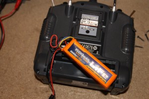
You’ll also need a screwdriver, to remove the six screws that close the transmitter:

 [/vc_column_text][/vc_tta_section][vc_tta_section title=”Let’s solder” tab_id=”1463101648209-8d0e921a-09fa”][vc_column_text]
Let’s solder
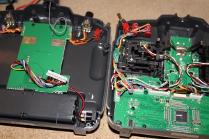
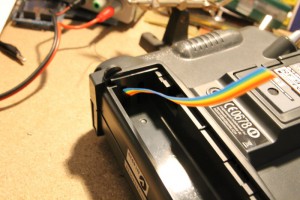
After having removed the six screws and the battery, you can open the transmitter. The two circuit boards are connected by a group of wires: you have to gently remove the connector to be able to separate the two halves:
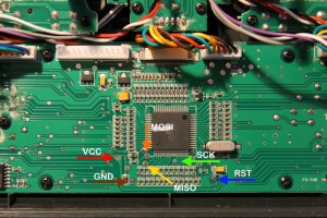
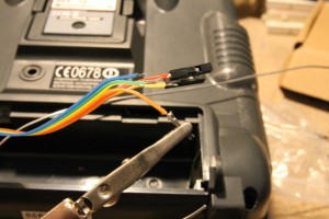
Now the most difficult part: you have to solder six wires (I used a colored flat cable) to six pads on the PCB. The six pads correspond to the SPI bus signals (and VCC and ground), used for programming the microprocessor. Here’s an image that explains which pads must be connected and their “meaning”:
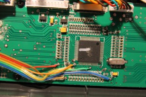
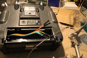
Some modders cut the plastic to glue a 6/8 pins connector; I prefer to insert the flat cable in the battery compartment (using the provided holes) and to solder to each wire a female connector:
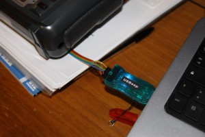
After having soldered all the connectors, you can connect them to the programmer:
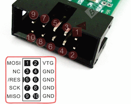
The USBasp pinout is at follows:
 [/vc_column_text][/vc_tta_section][vc_tta_section title=”Flash the frimware” tab_id=”1463101649051-0291e955-813a”][vc_column_text]
Flash the firmware
Download the eePe software from its official website and install it on your PC. When you run it, it should ask if you want to download the latest version of the er9x firmware; if not, you can download it manually.
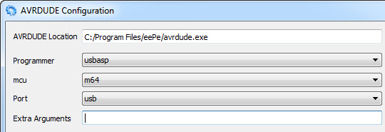
Check that the configuration (Burn – Configure) is as follows:
First, make a backup of the official firmware, saving the resulting hex file on your PC:

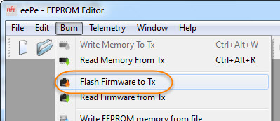
Now you can flash the er9x firmware:
Choose the .hex file previously downloaded:

Wait during the writing process:

Until you get the confirmation dialog:

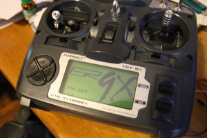
Unconnect the programmer and turn the transmitter on. It should say that the EEPROM content is invalid (it’s normal as you replaced the stock firmware with a custom one) and then the er9x splash screen should appear:
 [/vc_column_text][/vc_tta_section][vc_tta_section title=”User manual ” tab_id=”1463103256592-e2c6b236-9597″][vc_column_text]
User manual
At the end of this blog post, a link to a great user’s manual to understand all the features of this firmware!
For more details,please refer to original post
http://www.lucadentella.it/en/2015/05/24/caricare-il-firmware-er9x-sulla-trasmittente-turnigy-9x/
[/vc_column_text][/vc_tta_section][/vc_tta_tour][/vc_column][/vc_row]

Leave a Reply
You must be logged in to post a comment.