[vc_row][vc_column width=”1/1″][vc_tour][vc_tab title=”pcDuino” tab_id=”1389056110-1-67″][vc_column_text]Please visit: http://esdartemis.wordpress.com/ for the full story.
After researching auxiliary processors, we decided to use the pcDuino for controlling our drone. The choice was an obvious one because it was not only the lightest of the choices, but also one of the least expensive, and in addition was running Linux as well as providing a wireless card. On arrival we quickly connected it to a monitor, but the adapters we purchased did not work. So as result we shaved rubber off of one of the adapters so that it fit properly in the monitor to connect to the port. We were able to gather some of the peripherals(USB hub, mouse, and keyboard) key from our computer department for the project.
Our first task was to find a way to control the drone over wifi so that the pcDuino could send to the drone, commands essential for autonomous flight. We first installed node package manager onto the pcDuino so that we could use the command line prompt to install the packages we needed. The packages we intsalled were the node-ar-drone package , the NPM(node package manager) package, and the git package. The node-ar-drone package provides a library of javascript functions for the ar drone. NPM is responsible for loading and updating the packages. The git package allows us to retrieve packages from github.
The pcDuino would not automatically adjust its date on bootup. The date mismatch prevented us from accessing the internet. We use the command line prompt to set the date and time.
We did some research and found out that the drone could be controlled by executing java script files. We used a program called Node.js because there was plenty of documentation on controlling the drone with that program. We worked on forcing the pcDuino to connect to the drone on startup. After spending time on that task we found out that it connected to the drone automatically on start up.
We will attach a GPS sensor to the pcDuino for determining position of the drone. We will connect the GPS will be attatched to the pcDuino through a breadboard. The breadboard will have buttons that will initiate the startup of the drone control. Once the program is loaded the buttons will be our only source of control of the drone startup. We still need to figure out how to communicate between the GPS sensor and the java script program. Fortunately the pcDuino provides an Arduino IDE that we are familiar with using.
-Renner[/vc_column_text][/vc_tab][vc_tab title=”Arduino Programming” tab_id=”1389056110-2-71″][vc_column_text]Arduino is a popular circuit board with header pins for connecting to external hardware. It is programmed in C and is commonly used for robotics programming. The pcDuino comes with Arduino header pins and a built in programming environment that allows you to treat it as if it is an ordinary Arduino board, with the same programming and hardware setup.
The first use for these features we explored was the addition of buttons and indicator LEDs so that we can start up the pcDuino program without the need for a monitor or a mouse and keyboard. Using this Arduino tutorial, the pcDuino’s built-in Arduino IDE (Integrated Development Environment), and a breadboard and electronic parts from my personal hobby supply, we created a code that would turn an LED on when a button was pressed, and off when it was not. Here is a demonstration of this setup.
This was a nifty little experiment, but it really had no real long-term use. We really needed to pause the execution of the start-up script on the pcDuino (cleverly named startemis) and wait for a button press to continue. This created two main problems. First off, we had run the LED control code from within the Arduino IDE by clicking on a run button, and the whole idea of the button on start up was that we wouldn’t have to click anything on a screen. Therefore, we had to find a way to execute Arduino programs without a need for the IDE. Our second problem, which turned out to be much more difficult than we expected, was that to continue with the start up script after the button is pressed, the Arduino program has to end.
Most code, like a normal java, ruby, or C program, ends and exits when it reaches the end of its main method. However, Arduino, although based in C, is designed not to stop. Because it is meant for robotics and automation, the code loops until the power plug is pulled, and the coding of the main method is handled outside of the Arduino programming language. Therefore, the operations we would normally use to interrupt and end the program–like returning from the main method, or breaking the program loop so that the main method can end–simply don’t work. After searching the internet for a while(becoming a common theme) we found a simple way to end the code’s execution without using any of the aforementioned methods. The code waits for the button to be pressed, and then it causes an error that makes the code crash (in a controlled manner). To do this we created an integer variable with the value 0 and once the button was pressed, the code attempts to divide another number by this variable. As we all know, a number divided by zero is an undefined value, so the code crashes at this point, throwing a floating point exeption, essentially a divide by zero error, and then the start up script can continue. We are trying to find a better, cleaner way of exiting the code, but for now, dividing by zero will suffice.
Our other problem was that we had to find a way to execute the Arduino programs automatically from the start up script without needing to use the Arduino IDE. Again, after an hour or so of Google searches and failed endeavors, we stumbled accross a tutorial that showed the step-by-step installation and use of a software library called c_enviroment(yes that’s how it’s actually spelled) designed specifically for running Arduino programs on the pcDuino. After missing the misspelling of environment and pulling hairs for an hour or so because the URLs we were trying to access didn’t exist, we finally managed to install the environment and ran a test program successfully. The environment takes the Arduino code we write in normal C file, compiles it, and saves it to an executable file– instructions the pcDuino understands in binary format (1′s and 0′s)– that can then be run at any time from within the command line or a script like our start up script.
After solving those two problems, we created simple Arduino code that turns on an indicator LED, waits for a button press, and then self-destructs. We compiled it using c_enviroment and added it to the start up script so that the pcDuino waits for you to press a button before it tells the drone to take off.
Further down the road, we will use Arduino programming and hardware to receive data from GPS sensors, and we will likely add a couple more indicator lights to help us to more easily understand what is happening on the pcDuino without the need for a monitor. Also, we will eventually solder all the components to a circuit board that can be mounted to directly to the pcDuino for a more permanent and compact platform.
-Alexander[/vc_column_text][/vc_tab][vc_tab title=”Programming” tab_id=”1389056231459-2-8″][vc_column_text]One of the problems we had to overcome was the different programming languages of the Drone and the ArDuino. To communicate with the drone, we must use javascript, but the ArDuino and GPS is programmed in C++. So, we have to take the flight information from the GPS and relay that to the drone to go to a specified coordinate.
We bought a Paralax GPS sensor, which plugs in to the ArDuino ports on the PcDuino. We chose this GPS because its price was relatively low compared to other sensors and it still had all of the features that we needed. It has the ability to connect to up to 20 satellites, which makes it just as accurate as more expensive sensors. It also has support for the ArDuino and there is documentation for this sensor on the ArDuino playground.
Currently, we are working on getting data from the sensor. We are encountering a lot of errors with the code that we are slowly sorting out. Our ace programmer, Eggers, is on the case.
-Michael[/vc_column_text][/vc_tab][vc_tab title=”Software Flow” tab_id=”1389056257941-3-2″][vc_column_text]
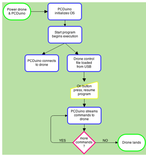
The chart above demonstrates the process of the PcDuino startup and execution of our program. I first tried to make the chart in a program called lucid but realized that after 15 days our free trial would expire and I would have to restart. We switched over to a website called diagram.ly which allowed us to make the flow charts for free. The chart describes the steps from the initialization of the operating system to the execution of our program that controls the drone.[/vc_column_text][/vc_tab][vc_tab title=”Circuit board” tab_id=”1389056287566-4-6″][vc_column_text]We needed a way to read inputs to the PcDuino so that the GPS sensor and buttons could be used. Buttons are used to control the drone start up; the GPS sensor is used to make adjustments in flight. We started out with a breadboard so that we could prototype the wiring. The breadboard was only temporary because the drone would not be able to carry it during its flight–it was too big and too heavy. After we finished prototyping the system, Alexander soldered the components to a circuit board. The circuit board is very light, and is a more permanent solution.
We are using buttons, LEDs, and the GPS sensor in our circuit configuration. The buttons are used to start the drone flight when the PcDuino is done booting up. The LEDs serve as a visual representation to indicate when the PcDuino has finished booting and the the program is ready to be executed. The GPS sensor will allow the PcDuino to make in flight adjustments by sending it coordinates.
Video of Alexander soldering
http://www.youtube.com/watch?v=UfhYALwnHNU&noredirect=1
-Renner[/vc_column_text][/vc_tab][vc_tab title=”PcDuino Mount” tab_id=”1389056322643-5-1″][vc_column_text]

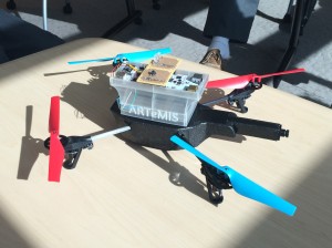
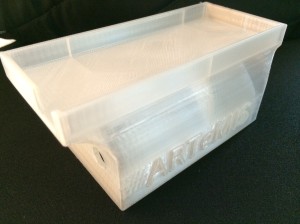
For our Computer Science project, we needed a way to mount a microcomputer onto the Parrot AR Drone that we are programming. The best way for us to do so was by creating and 3D printing a mount that can replace the Styrofoam hull that comes with the drone. The mount that we printed fits snugly over the battery of the drone, so it also protects the battery if the drone crashes. It also has a slot for the USB and power cables to go to the computer and there is a hole just below that so that we can run lines to the battery. To top it off, the project name ARTeMIS is typed on the side of the mount.
When I was modeling it on the computer, I had to measure the dimensions of all of the components that the mount is covering. Once I had the general shape that would fit, there were flat overhangs that would have failed in the printer because it can’t print flat surfaces in the air. To fix this, I put filets on those corners, which turned the flat surfaces into more manageable curved surfaces that the printer could print.
-Michael[/vc_column_text][/vc_tab][vc_tab title=”Software Problems” tab_id=”1389056358299-6-8″][vc_column_text]We have been working on getting the GPS sensor to work for a couple of weeks now. We are trying to read the serial input from the GPS sensor, but we must also output that serial to the terminal at the same time. This requires us to use softwareSerial, which is a library written by the ArDuino developers. First we had issues finding the files that were needed for it to run. After finding the needed files, we had massive compile errors that indicated that our PcDuino board wasn’t supported by the softwareSerial.
Instead, we are now trying to use the built in serial library to receive data from the GPS. This has compiled, but we are having an issue communicating with the terminal. We need a different baud rate, which is the rate at which data packets are transferred.
-Michael[/vc_column_text][/vc_tab][/vc_tour][/vc_column][/vc_row]

Leave a Reply
You must be logged in to post a comment.