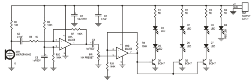
1) The first opamp is inverting with such a low input resistance of 1k ohms that it kills most of the signal from the higher resistance electret microphone. This opamp should be non-inverting with a much higher input resistance.
2) The coupling capacitor C4 between the opamps couples positive and negative AC to the input of the second opamp. But the maximum allowed negative input voltage is only -0.3V so the much higher negative part of the signal will probably damage the input.
3) The entire output current of the second opamp slams into the bases of the transistors without any current limiting that overloads the opamp and might damage the bases of the transistors.
The original post is from
http://electronics-lab.com/community/index.php?/topic/41376-sound-to-light-effect/
Leave a Reply
You must be logged in to post a comment.