In a previous post, we show how to use Linker ADC shield on Raspberry Pi to read ADC value. In this post, we show how to get dual channels from the Linker ADC shield.
We connect two Linker potentiometer modules to the Linker ADC shield as below:
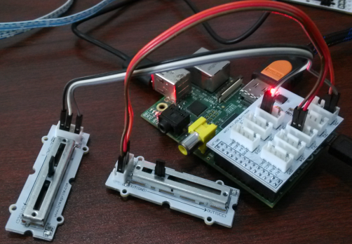
In detail, they are connected in the following way:
- LinkerPotentiometer① – VCC –> Base Shield For RPi VCC
- LinkerPotentiometer① – GND –> Base Shield For RPi GND
- LinkerPotentiometer① – OUT –> Base Shield For RPi (JP1-A0)
-
LinkerPotentiometer② – VCC –> Base Shield For RPi VCC
-
LinkerPotentiometer② – GND –> Base Shield For RPi GND
-
LinkerPotentiometer② – OUT –> Base Shield For RPi (JP1-A1)
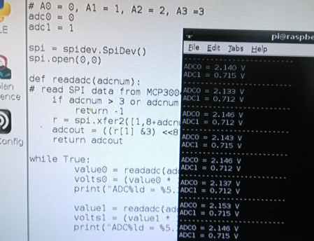
The python script is shown below:
import spidev
import time

# A0 = 0, A1 = 1, A2 = 2, A3 =3
adc0 = 0
adc1 = 1

spi = spidev.SpiDev()
spi.open(0,0)

def readadc(adcnum):
# read SPI data from MCP3004 chip, 4 possible adc's (0 thru 3)
    if adcnum > 3 or adcnum < 0:
        return -1
    r = spi.xfer2([1,8+adcnum <<4,0])
    adcout = ((r[1] &3) <<8)+r[2]
    return adcout

while True:
value0 = readadc(adc0)
volts0 = (value0 * 3.3) / 1024
print("ADC%ld = %5.3f V" % (adc0,volts0) )

value1 = readadc(adc1)
volts1 = (value1 * 3.3) / 1024
print("ADC%ld = %5.3f V"% (adc1,volts1) )

print("-------------------------")
time.sleep(0.5)
The results are shown below:
Leave a Reply
You must be logged in to post a comment.