[vc_row][vc_column width=”1/1″][vc_column_text]
Cottonwood: USB Long Range UHF RFID reader
Product Description
Long Range UHF RFID Reader is an important way to read information and input information. Automatic identification technology has been developed in recent years. Now it is a new high technology which includes barcode technology, magnetic strip (card) technology, RF technology, optical character recognition technology, and biological recognition, distance Card Reader and etc.
In normal case, UHF RFID tags need less power than the reader which needs to have high receiving sensitivity. In certain system, the transmit path and receive path are independent of each other in the reader, especially when the uplink and downlink have different frequency.
Technically, different applications can choose different transmit power. However, there are regulations that need to be met. Usually the RF power 100mW~500mW is suitable for all kinds of RFID distance reader system. In different regions and areas, the reader has to follow different regulations.
Cottonwood distance reader has many advantages such as: compatibility with different protocols, high reading speed multi-tags reading, linearly polarized antenna, waterproof appearance designing and etc. It can be widely used in RFID systems, and is very friendly to further development based on it.
Typical applications:
-
Logistics and warehouse management: Management of goods flow and storage, and mail, package, luggage transportation and etc.
-
Intelligent parking management:Parking management and charge automation.
-
Production-line management: Identification of production process points.
-
Product anti-counterfeiting detection: the write protection from tag’s internal memory can be used to detect the products’ authenticity
-
Other application: widely used in club management, libraries, student status, consumption management, swimming pool management and etc.
-
When the UHF RFID reader is powered on and connected to PC, it can be identified by the PC software. It means the reader is working normally. When the tag is close to the reader, the PC software will show signal strength and tag ID. This RFID reader can identify many tag IDs at the same time.
-
This UHF RFID reader uses RF energy harvest to read tag data. Keep it far away from metal when use it. If it closes to the metal, the RF wave will be absorbed by it which can shorten the distance of card reading. The installation position should be away from the equipment like motor, transformer and etc, to reduce the effect on the reader.
-
According to the actual needs, this UHF RFID reader can be with the most suitable directional antenna with appropriate gain (5.5dBi, 8dBi and etc) to achieve the best performance.
-
There are two different interfaces: TTL UART and USB.
Recommended Antenna:
- 8dB mini: http://store.cutedigi.com/uhf-rfid-reader-antenna-902-928mhz-8dbi-rhc-pol/
- 8dB Full: http://store.cutedigi.com/uhf-rfid-reader-antenna-902-928mhz-8dbi-lhc-pol/
- 5dB mini: http://store.cutedigi.com/5dbi-pcb-uhf-rfid-902-928m-antenna-5cm-x-5cm/
Recommended Wall Adapter:
Specifications:
| Working Frequency | China standard (920~925MHz), American standard (902~928MHz), European standard (865~868MHz) , 840MHz~960MHz working frequency |
| Protocol | ISO18000-6C (EPC GEN2), compatible ISO18000-6A/B |
| Antenna gain | 5dBi or 8dBi directional antenna |
| RF power | MAX 20dBm |
| Card reading distance | Passive tags identification distance adjusting range:1 to 6 meters |
| Card reading time | Reading time of multi-tags 64 bit ID <6ms |
| Modulation mode | ASK or PR-ASK |
| Antenna interface | MMCX |
| Supporting interface | High speed USB or TTL Uart (RS232) communicate with PC applications |
| Power Supply | DC+3.3V 2A; +5.5V optional |
| Read indicator | Can be programmed. GPIO output can be set |
| Power | 1.5W-2W |
| Working temperature | -20 degree C +80 degree C |
| Storage temperature | -40 degree C to +125 degree C |
| Working humidity | 20% to 95 % (No condensation) |
| Dimensions | 90mm×49mm×0.51mm |
[/vc_column_text][vc_tour][vc_tab title=”USB and UART version” tab_id=”1393554683-1-64″][vc_column_text]
Our RFID reader has 2 versions: USB and UART.
USB version: Cottonwood: Long Range UHF RFID reader UART (ISO18000-6C EPC G2)
UART version: Cottonwood: USB Long Range UHF RFID reader (ISO18000-6C EPC G2)
At the same time, the board only supports one way to communicate. So when you take the reader of UART version, it’s USB interface can not be recognized. The when you take the reader of USB version, it’s USB interface can not be recognized too.
You can switch the version through burning the corresponding firmware. The reader module has C2 programming interface of C8051 MCU. You can get all the .hex documents of the two version . You can program the MCU by yourself.
The .hex file we provide see below:
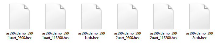
Download all the .hex files : AS399X_usb_and_uart_firmware.zip
1) “as399xdemo_3991uart_9600.hex” and “as399xdemo_3992uart_9600.hex” are
the firmwares to set the reader UART version with 9600bps baud rate.
2) “as399xdemo_3991uart_115200.hex” and “as399xdemo_3991usb.hex” are the
firmwares to set the AS3991 reader UART version with 115200bps baud rate
and USB version.
3) “as399xdemo_3992uart_115200.hex” and “as399xdemo_3992usb.hex” are the
firmwares to set the AS3992 reader UART version with 115200bps baud rate
and USB version.
[/vc_column_text][/vc_tab][vc_tab title=”Burn USB version” tab_id=”1393573209002-1-9″][vc_column_text]
Burn USB version
Choose “as399xdemo_3992usb.hex ”
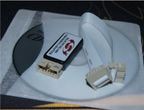
1. First select on C8051 programmer of silicon, we choose the one below:
you can buy a C8051F simulator, like this: Silabs Compatible USB Debug Adapter
2. When you write .hex file into the reader’s MCU directly to install Flash Programming Utilities by http://www.silabs.com/products/mcu/Pages/8-bit-microcontroller-software.aspx#flash
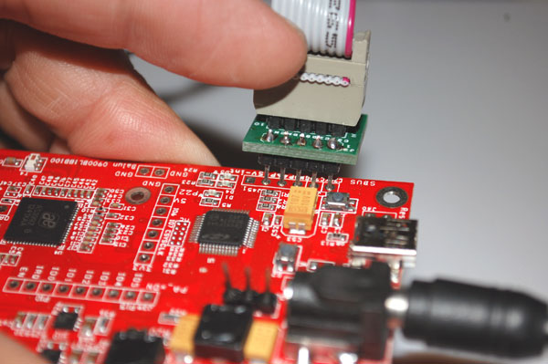
3. Connect the hardware, open the programmer’s PC software, then begin to burn.
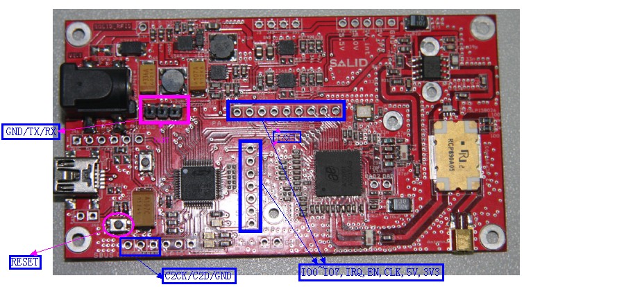
Hardware connection:
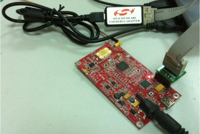
4.Begin to program
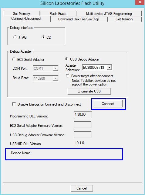
1) Open the programmer’s PC software, select “Connect/Disconnect”, connect this simulation to C8O51F34O MCU of the reader,
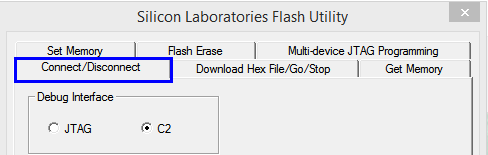
2) Click “Connect”
3) Connect successfully, select “Download Hex File/Go/Stop”,
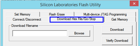
click “Browse” to choose the .hex file you want to write. we choose ” as399xdemo_3992usb.hex ”
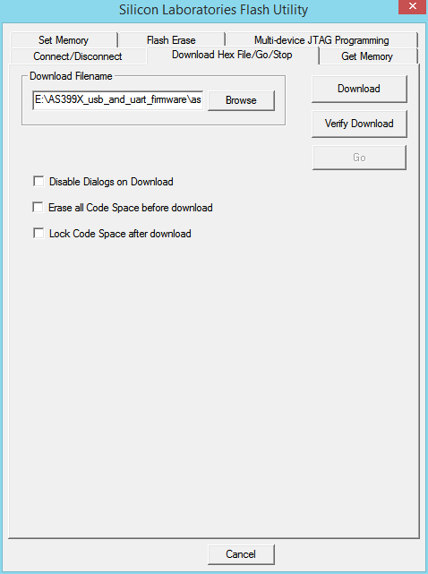
4) Click “Download “, begin to program the MCU, see below:
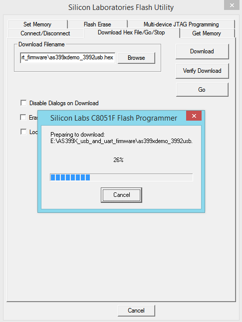
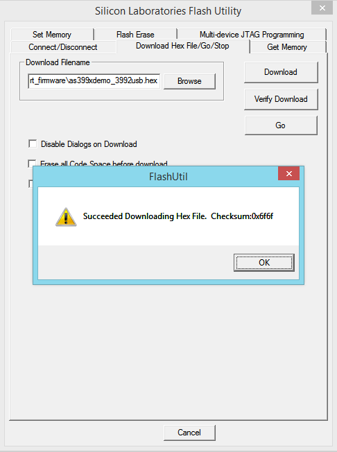
Program successfully.
5) Disconnect the programmer
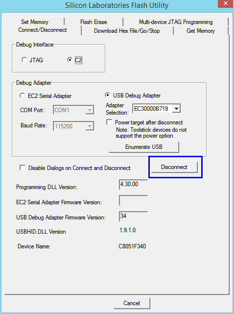
Note:
This “Disconnect” button is to utterly disconnect the simulator and reader, After disconnection, the MCUwill run the program. If yours does not show this, you can broken the reader’s prower then plug in again or press the “S1” button for reset.
[/vc_column_text][/vc_tab][vc_tab title=”Burn UART Version” tab_id=”1393576843809-2-9″][vc_column_text]
Burn UART version
Choose “as399xdemo_3992uart_115200.hex ”
1. Fist select on C8051 programmer of silicon, we choose the one below:
you can buy a C8051F simulator, like this: Silabs Compatible USB Debug Adapter
2. When you write .hex file into the reader’s MCU directly to install Flash Programming Utilities by http://www.silabs.com/products/mcu/Pages/8-bit-microcontroller-software.aspx#flash
3. Connect the hardware, open the programmer’s PC software, then begin to burn.
Hardware connection:
4.Begin to program
1) Open the programmer’s PC software, select “Connect/Disconnect”, connect this simulation to C8O51F34O MCU of the reader,
2) Click “Connect”
3) Connect successfully, select “Download Hex File/Go/Stop”,
click “Browse” to choose the .hex file you want to write. we choose ” as399xdemo_3992uart_115200.hex ”
4) Click “Download “, begin to program the MCU, see below:
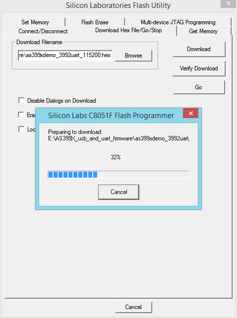
Program successfully.
5) Disconnect the programmer
Note:
This “Disconnect” button is to utterly disconnect the simulator and reader, After disconnection, the MCUwill run the program. If yours does not show this, you can broken the reader’s prower then plug in again or press the “S1” button for reset.
[/vc_column_text][/vc_tab][/vc_tour][/vc_column][/vc_row]
Leave a Reply
You must be logged in to post a comment.