[vc_row][vc_column width=”1/1″][vc_column_text]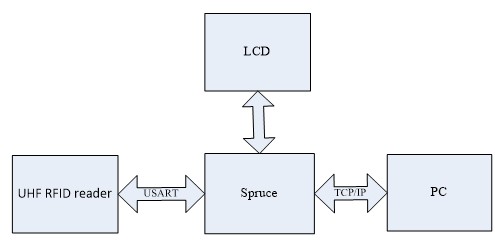 [/vc_column_text][/vc_column][/vc_row][vc_row][vc_column width=”1/1″][vc_tour][vc_tab title=”Hardware list” tab_id=”1389233718-1-79″][vc_column_text]
[/vc_column_text][/vc_tab][vc_tab title=”System installation” tab_id=”1389233718-2-24″][vc_column_text]
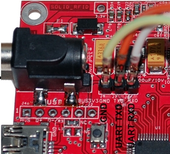
1.Spruce is connected to UHF RFID through 3 lines:
The jump wire connection is as follows:
- Spruce GPIO pin 40 -> UHF RFID GND
- Spruce GPIO pin 14 -> UHF RFID RXD
- Spruce GPIO pin 15 -> UHF RFID TXD.
2. USB line is connected to PC or other USB HOST. It provides 5V power to Spruce (in actual using; you can use the 3V power on UHF-RFID as the working power of Spruce’s)
3. 5V/2A power adaptor provides working power to UHF-RFID.
4. UHF-RFID antenna interface is connected to antenna RFID 902-928MHz.
5.RJ45 is connected to Ethernet interface on PC.
 [/vc_column_text][/vc_tab][vc_tab title=”Sample Code” tab_id=”1393270964797-3-0″][vc_column_text]The sample code can be downloaded from github at: https://github.com/linksprite/cottonwood/tree/master/Spruce-RJ45-RFID[/vc_column_text][/vc_tab][vc_tab title=”Environment configuration” tab_id=”1389234274059-2-8″][vc_column_text]1. Configure PC’s IP:
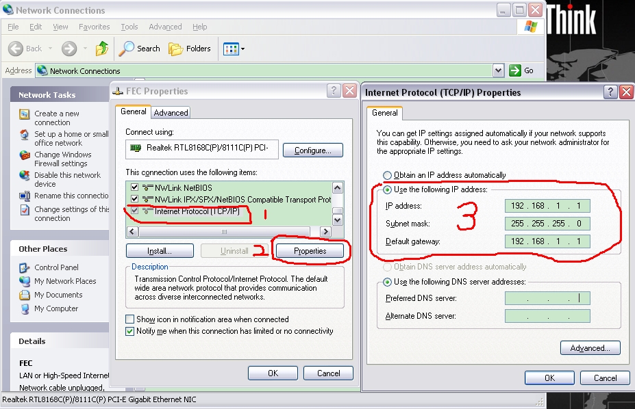
Set TCP/IP protocol at PC. Manual configuration
IP address : 192.168.1.1
Subnet mask:255.255.255.0
Default gateway:192.168.1.1
2 . PC communicates with UHF RFID Reader through Ethernet
The TCP IP test tool can be downloaded here usr-tcp232-test
The following is a screen shot of using TCP to read the tag:
1. In NetSetting, do the configuration
Protocol : TCP Client
Server IP : 192.168.1.15
Server Port : 1200
2. Click Connect
3. In the window Network Data receive comes “ Great! connect success! ”, which means connection is successful.
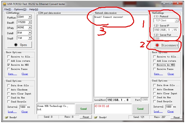
Tag scanning:
- Set HEX sending and receiving
- Input tag scanning command: 43 04 01 cd and click “Send”
- Network Data receive window returns the tag ID
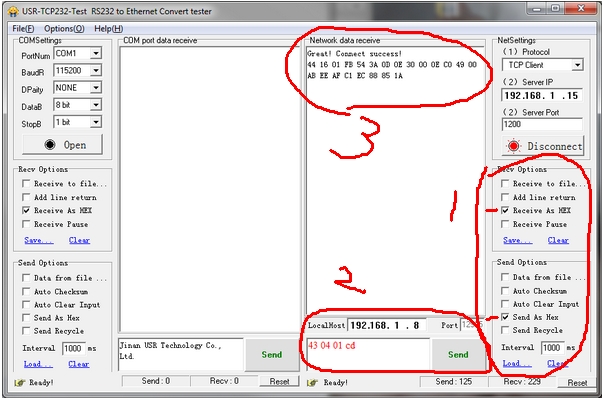
By decoding the message, we can see that one tag is found,
Multi-operation command, please see the Uart RFID control commands set
[/vc_column_text][/vc_tab][/vc_tour][/vc_column][/vc_row]
Leave a Reply
You must be logged in to post a comment.