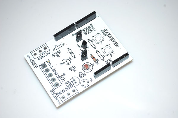
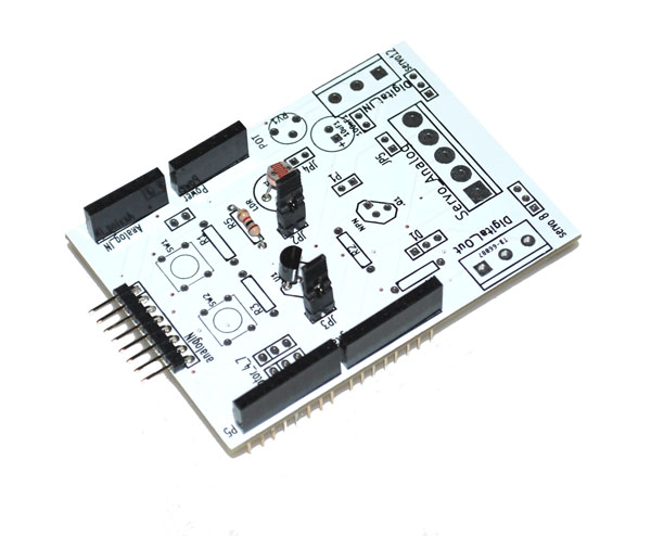
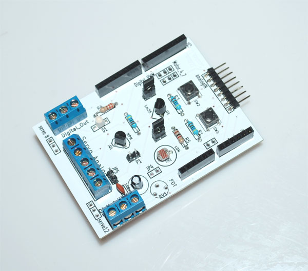
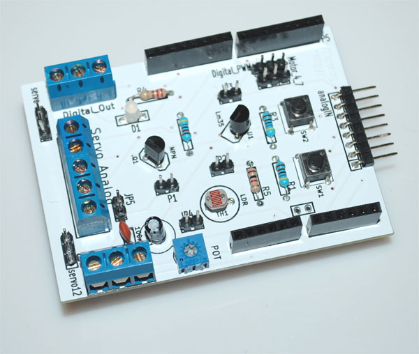
[vc_row][vc_column width=”1/1″][vc_column_text]![]()
This scratch IO shield kit is designed by https://scratch-io.wikispaces.com.
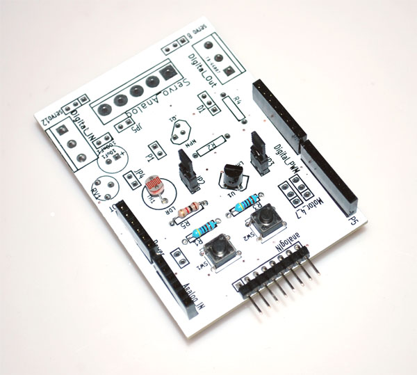
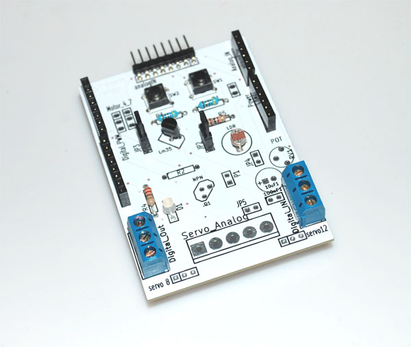
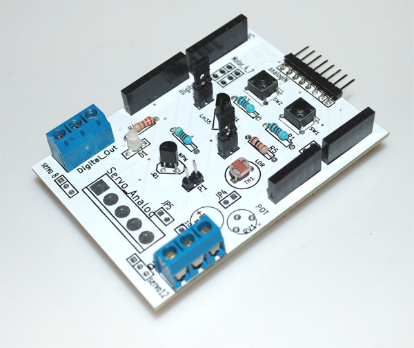
The simple board is easy to solder and is then ready to use in an infinite number of projects. It contains some analog sensors onboard: light sensor, temperature sensor an angle sensor (potentiometer); some digital sensors: two push buttons. Also included, as digital output, a bi-color LED and analog power driver base on NPN transistor.
There is a full range of connectors where you can plug your own sensors and actuators. This tool it is perfect for programing students, and Robotic workshops. It has been designed by teachers of the Robotics lab of Colegio San Gredos in Alcalá de Henares, Madrid, Spain. It has been developed under the OpenHardware spirit, and it is given to the community to enjoy and to be improved. This scratch_io hardware runs linked to a Scratch modification made by S4A group from citilab (free downloadable). The standard Scratch version from MIT does not support it (soon, we expect it will be supported).
Let´s teach young people how to discover hardware and robotics in a friendly manner, let’s teach them how to build a better future.
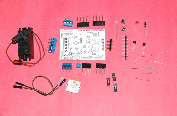 [/vc_column_text][vc_tour][vc_tab title=”Parts List” tab_id=”1388007864-1-77″][vc_column_text]The following are included:
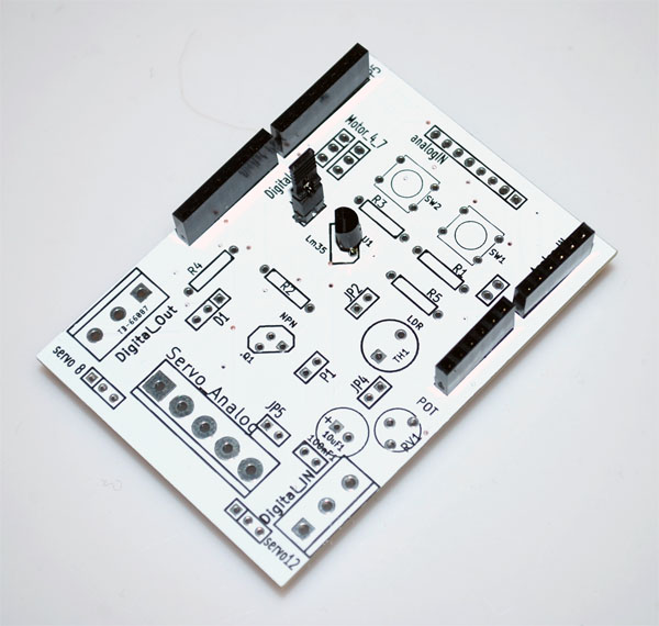
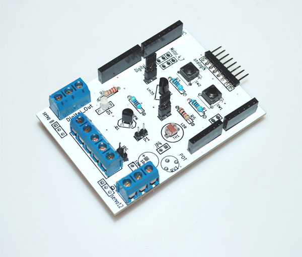
1. PCB
2. Components:
- 100nF C
- 10uF 5vol CAPAPOL
- D1 DOUBLE_LED Led bicolor
- K1 conector PCB con tornillo 3vias
- K2 conector PCB con tornillo 3vias
- P1 Tira pines simple 2,54mm (50pines)
- Q1 BC547
- R1 5k 1/4w
- R2 5k 1/4w
- R3 5k 1/4w
- R4 220ohm 1/4w
- R5 1K 1/4w
- RV1 POTENCIOMETER Vertical 10k
- SW1 SW_PUSH_SMALL. Pulsador para PCB
- SW2 SW_PUSH_SMALL. Pulsador para PCB
- TH1 LDR
- U1 Lm35
- Jumper 2,54… (4 units)
- Linker LED module
- RC continuous servo
[/vc_column_text][/vc_tab][vc_tab title=”Analog Input” tab_id=”1388007864-2-46″][vc_column_text]On the Scratch IO shield, we have two analog sensors, one temperature (LM35) sensor and one light (LDR) sensor, with them we can easily make a weather station which tells temperature and hours of daylight and darkness each day.
These sensors can be disconnected with the jumpers that we have on the shield.
LM35:
First, we will solder the LM35 and related components as below:
We grab the pieces we want, and put together the following code:
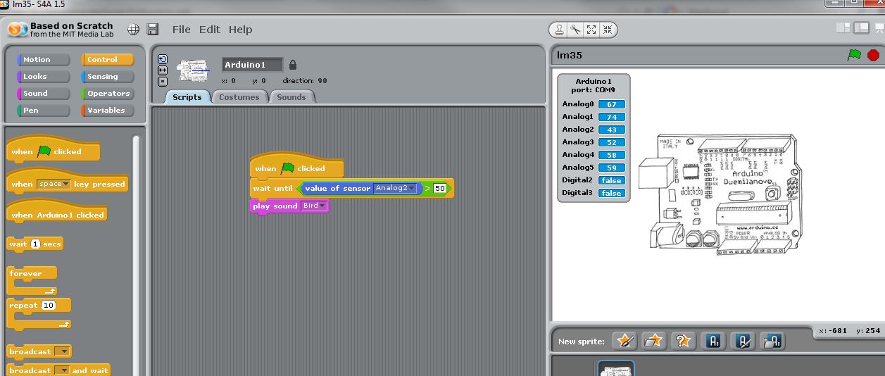
The project can be downloaded from lm35.
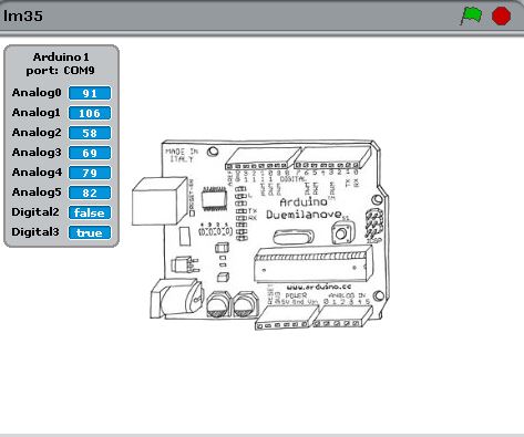
When lm35 sites on room temperature, the ADC (Analog2) reading will be less than 50.
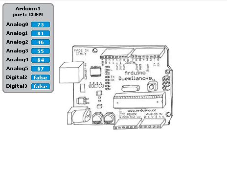
When we touch lm35 with a warm hand, the ADC reading (Analog2) will be larger than 50. At the same time, the bird will sing!
A wake up rooster by LDR:
Now we are going to make a wake up rooster.
We continue to solder the LDR and related components onto the shield:
On software side, the code will be:
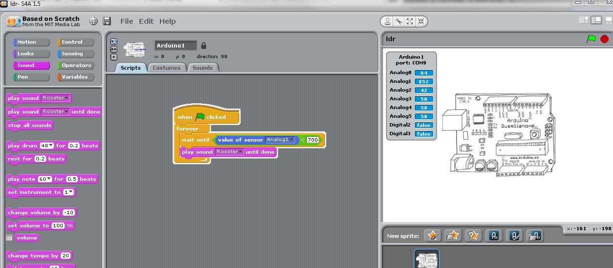
You can also download the project ldr.
When the LDR is covered, the ADC reading (Analog1) is large.
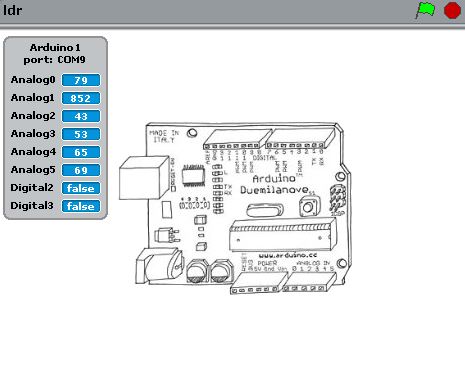
When the cover is removed, i.e., the sun rises, the ADC (Analog1) reading will be small,
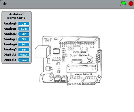
When the ADC reading is smaller, the rooster will wake you up!
More analog inputs:
Scratch provides the following variables:
- Analog1
- Analog2
- Analog3
- Analog4
- Analog5
- Analog6
These variables are also connected to the analog inputs of the shield. On the shield, we have a connector with all analog input lines, Vcc and ground. We can make our sensors to interact with the software. Our next step is to solder the headers onto the shield:
[/vc_column_text][/vc_tab][vc_tab title=”Digital Input” tab_id=”1388016729054-2-6″][vc_column_text]Now we continue the journey by populating two buttons and two resistors as following:
The s4s project will look as following:
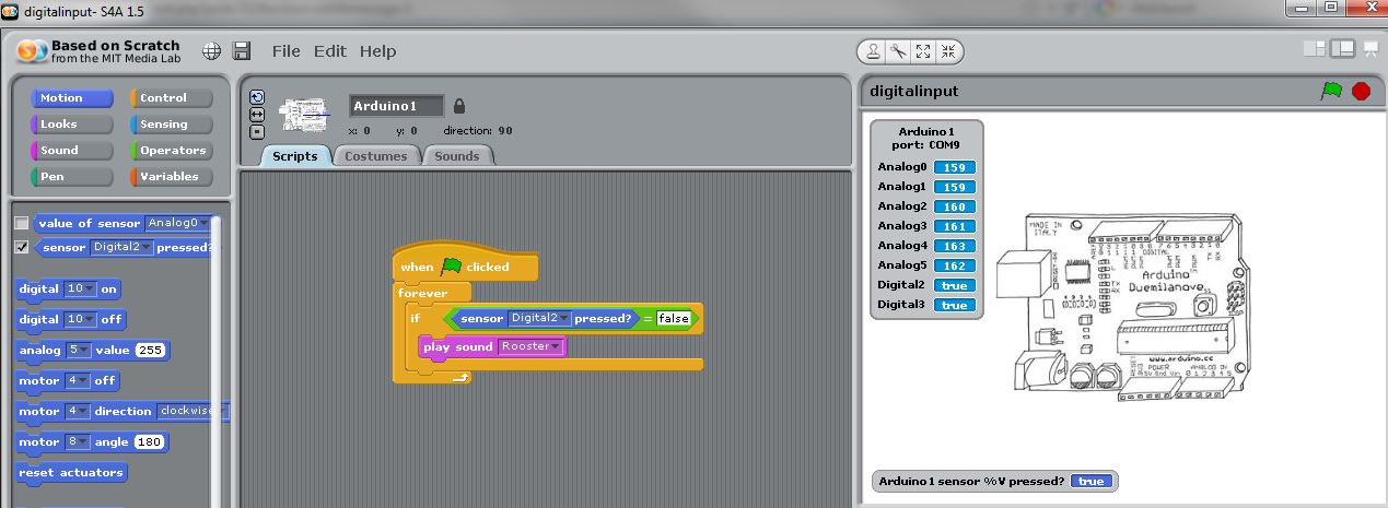
You can also download the project at digitalinput.
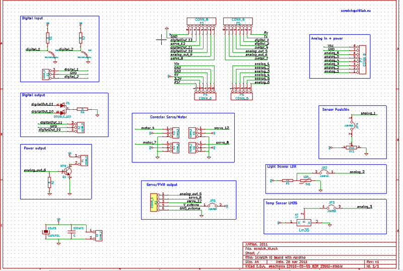
When the buttons are pressed, the value is ‘false’, and it becomes ‘true’, when released. This can be explained by the schematic, i.e, when pressed, digital 2/3 will be tired to ground.
So when we press the button, the rooster will sound.
Other digital inputs options:
Besides the two buttons, we can wire the external digital inputs to the connector. Now we will install the connector as following:
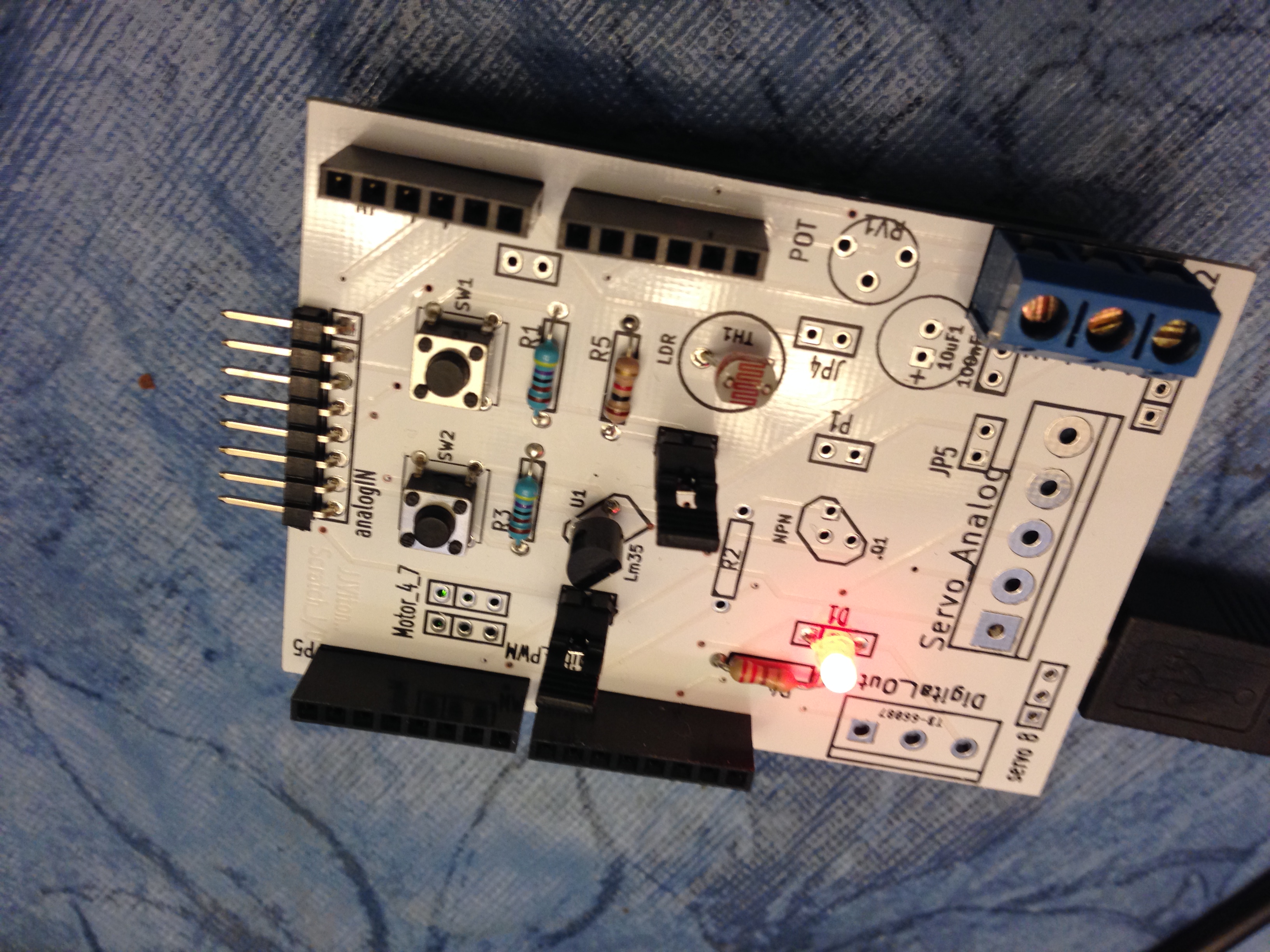
 [/vc_column_text][/vc_tab][vc_tab title=”Digital Output” tab_id=”1388018637530-3-0″][vc_column_text]We continue to populate digital output components, the LED and resistor R4:
When we use s4a to turn on digital10 high,
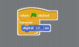
the LED will turn green,
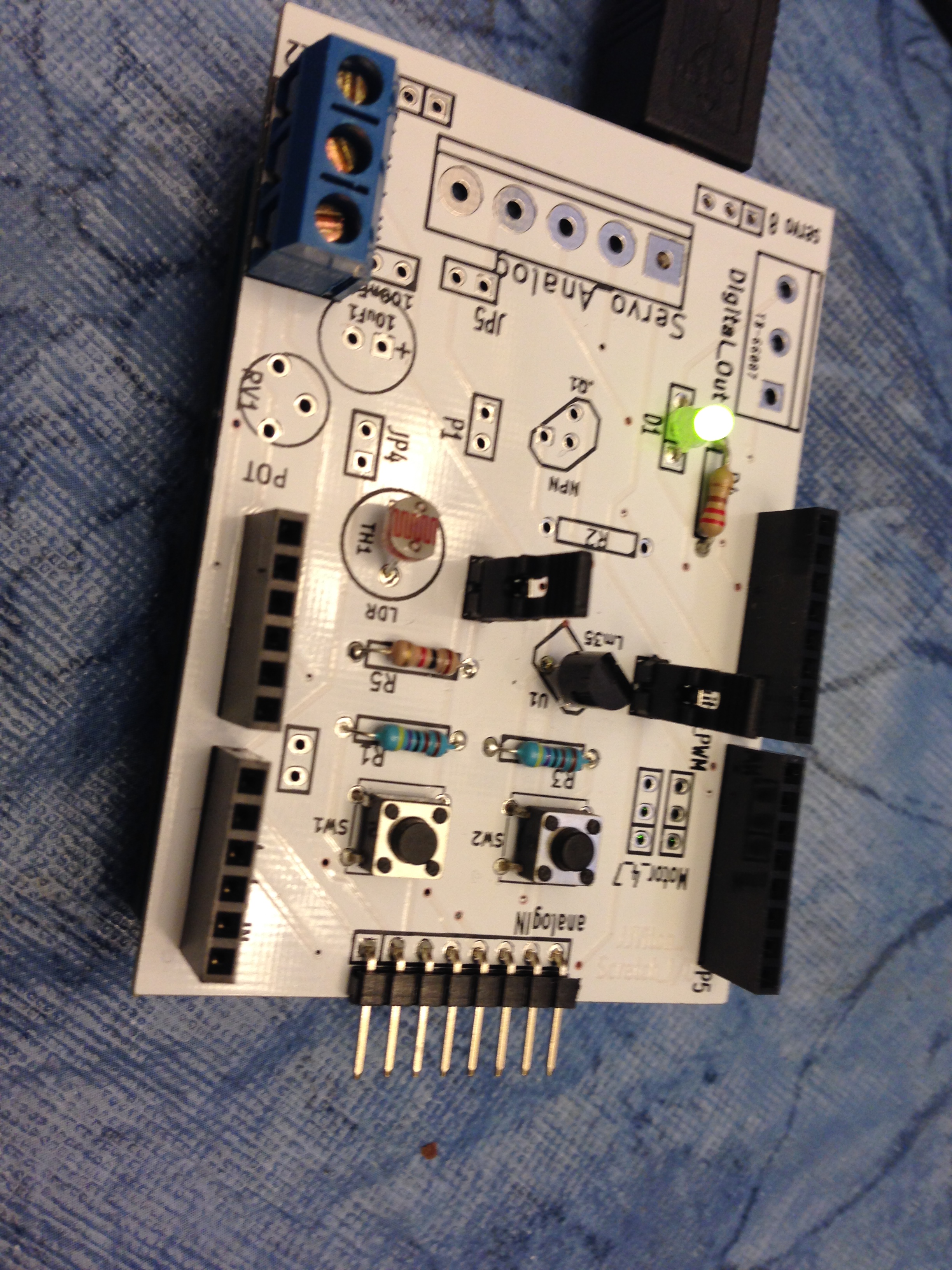
When we use s4a to turn digital11 high,
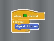
the LED will turn red,
Other digital output options:
As before, we can install the digital output connector to facilitate more digital output options.
[/vc_column_text][/vc_tab][vc_tab title=”Analog Output” tab_id=”1388026559485-4-6″][vc_column_text]Now we venture into the analog output area by continuing to populating the NPN, resistor, and connector P1 that is used to hook up external device:
We connect a Linker LED module to connector P1:
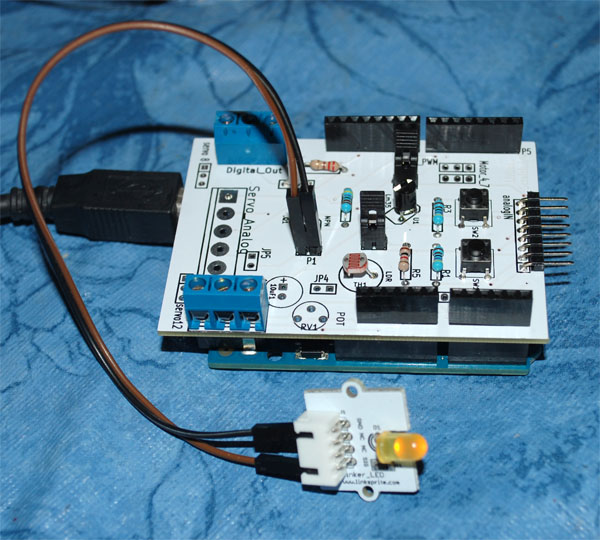
We create a scratch program to randomly change the brightness of the LED:
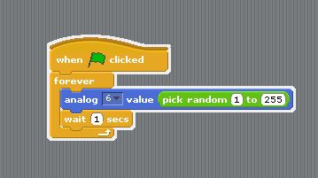
High the green flag, we will observe the brightness of LED changes randomly.
More analog output options:
We will continue to populate the shield with additional connectors that allow for more analog output options.
[/vc_column_text][/vc_tab][vc_tab title=”Oops…” tab_id=”1388033033081-5-4″][vc_column_text]At this point, we found that we missed two decoupling caps that need to be installed at the first place. Let’s do that now:
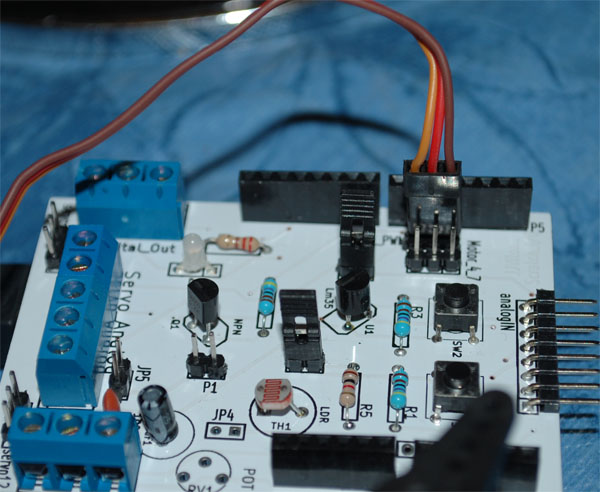
 [/vc_column_text][/vc_tab][vc_tab title=”Servo” tab_id=”1388033579880-6-2″][vc_column_text]Now we move on to the exciting part. We will drive a servo motor! Before we do that, let’s solder the headers:
let’s take a continuous servo, and plug into servo 4:
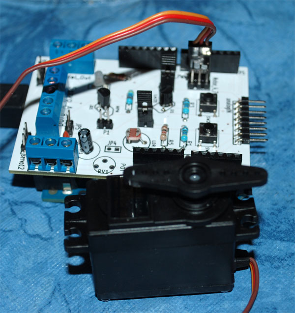
Please pay attention to the color of the wire:
We put together the scratch project like:
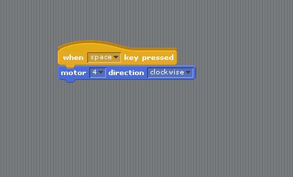
Hit the little green flag, the servo will keep rotating clockwise!
[/vc_column_text][/vc_tab][vc_tab title=”Revisit Analog Input” tab_id=”1388039112245-7-7″][vc_column_text]We are almost done. Now let’s populate the last piece of analog input device, the potentiometer:
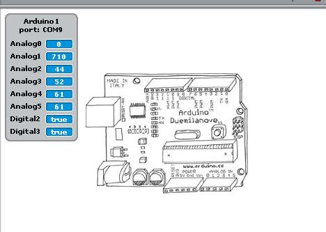
When we use a screw driver to turn the potentiometer to the right most position, we will see ADC0 reading is zero:
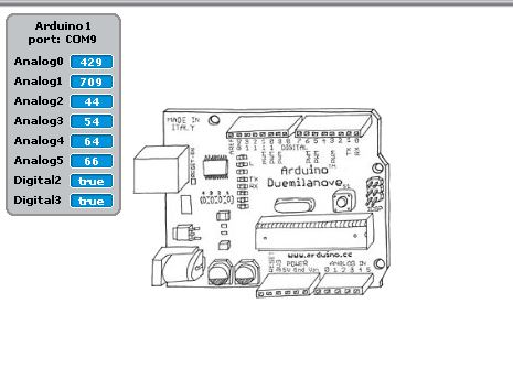
When we turn it back to the somewhere in the middle, we get another reading:
This concludes our tutorial. Hope you enjoy it!
[/vc_column_text][/vc_tab][/vc_tour][/vc_column][/vc_row]
Leave a Reply
You must be logged in to post a comment.