This recipe is originally from: http://www.geek-workshop.com/thread-5140-1-1.html
There are now many LED display, but most are based on the same type of drive, 08 short drive, it has an internal LED matrix, 74HC595, 138 sweeping lines chips, but without exception, is the control board have adopted the STC program, or the serial scheme, while Arduino drive has few people to use,Now let’s see the introduction and analytical LED industry standard Arduino drive scheme.

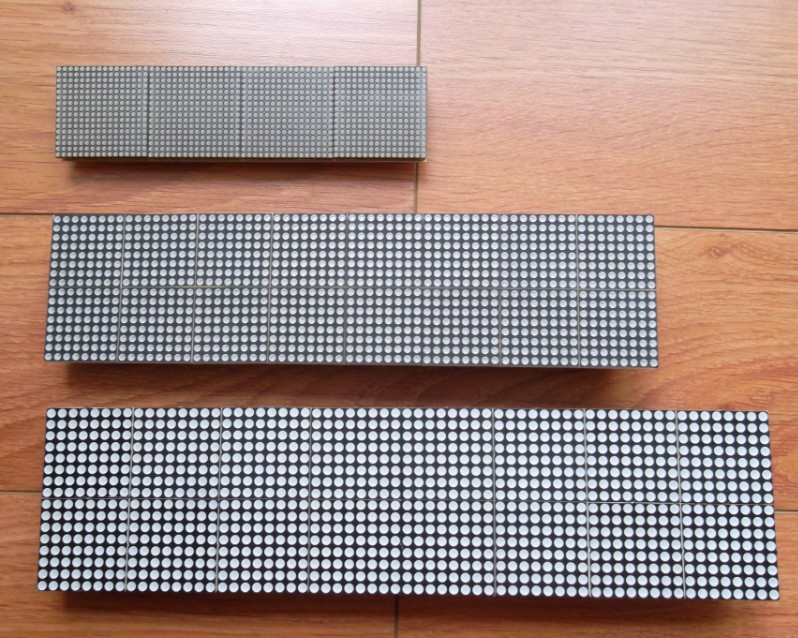
Different type of LED matrix
Market Shang mainstream of display has F3.75 and F3.0 two species, f behind representative of lattice screen monomer LED of diameter, and today, small z with of is F2.0 of Super intensive imports lattice, displayed effect personal is like, following is market Shang common of 2 species screen (F3.75 F3.0) and today by using of F2.0 screen (resolution are for 16*64) of compared figure, can is easily of see size of difference.
Driving mode
Then the focus is driving mode, I suggest two driving modes, namely 16*16 drive mode, and 16*64 direct drive mode, these two modes have different characteristics, 16*16 is the Chinese character is a modulus, oneshow, and 16*64 is taken directly out of a full image of the software. If the students is to display the Chinese characters, first is recommended, and display graphics students, second is recommended.
Demo code:
#define RowA 2
#define RowB 3
#define RowC 4
#define RowD 5
//ABCD 08 driving mode
int hc138en=6; //EN IO

//use SPI
#define R1 11          //   MOSI
#define CLK 13         //    SCK
#define STB 10         //  SS
#define DATAIN  12     //  MISO

byte row=0;
byte zzz[] =

{
0x00,0x00,0x00,0x00,0x00,0x00,0x00,0x00,0xFF,0xF1,0xFF,0xE3,0xFF,0xC0,0x00,0x00,
0xFF,0xF1,0xFF,0xE3,0xFF,0xC0,0x00,0x00,0x00,0x70,0x00,0xE0,0x01,0xC0,0x00,0x00,
0x00,0xE0,0x01,0xC0,0x03,0x80,0x00,0x00,0x01,0xC0,0x03,0x80,0x07,0x00,0x00,0x00,
0x03,0x80,0x07,0x00,0x0E,0x00,0x00,0x00,0x07,0x00,0x0E,0x00,0x1C,0x00,0x00,0x00,
0x0E,0x00,0x1C,0x00,0x38,0x00,0x00,0x00,0x1C,0x00,0x38,0x00,0x70,0x00,0x00,0x00,
0x38,0x00,0x70,0x00,0xE0,0x00,0x00,0x00,0x70,0x00,0xE0,0x01,0xC0,0x00,0x00,0x00,
0xE0,0x01,0xC0,0x03,0x80,0x00,0x00,0x00,0xFF,0xF1,0xFF,0xE3,0xFF,0xC0,0x00,0x00,
0xFF,0xF1,0xFF,0xE3,0xFF,0xC0,0x00,0x00,0x00,0x00,0x00,0x00,0x00,0x00,0x00,0x00
};


void spi_transfer(volatile char data)
{
  SPDR = data;                    // Start the transmission
  while (!(SPSR & (1<<SPIF)))     // Wait the end of the transmission
  {
  };
  //return SPDR;                    // return the received byte
}


void hc138sacn(byte r){  //(A LOW,D HIGH)
 digitalWrite(RowA,(r & 0x01));
    digitalWrite(RowB,(r & 0x02));
    digitalWrite(RowC,(r & 0x04));
    digitalWrite(RowD,(r & 0x08));
}

void hc595senddata(byte data){
 for (byte i=0; i<8;i++) {
     digitalWrite(CLK,0);
     if (data & 0x80) {
         digitalWrite(R1, 0);
     } else {
         digitalWrite(R1, 1);
     }
     data=data<<1;
     digitalWrite(CLK,1);
 }

}


void setup () {

    pinMode(RowA, OUTPUT);
    pinMode(RowB, OUTPUT);
    pinMode(RowC, OUTPUT);
    pinMode(RowD, OUTPUT);
    pinMode(hc138en, OUTPUT);

    pinMode(R1, OUTPUT);
    pinMode(CLK, OUTPUT);
    pinMode(STB, OUTPUT);
    pinMode(DATAIN, INPUT);


     //digitalWrite(hc138d, HIGH);
    Serial.begin(19200);

    //SPI configuration
    // SPCR = 01010000
    //interrupt disabled,spi enabled,msb 1st,master,clk low when idle,
    //sample on leading edge of clk,system clock/4 rate (fastest)
    SPCR = (1<<SPE)|(1<<MSTR);
    delay(10);
}

void loop () {
if (Serial.available() > 0) {
// read the incoming byte:
row = Serial.read();

// say what you got:
Serial.print("I received: ");
Serial.println(row, DEC);
}

  for(row=0;row<16;row++){

      for (int i=0;i<8;i++){
         spi_transfer(~(zzz[i+row*8]));
      }


      digitalWrite(hc138en, 1);
      hc138sacn(row);
      digitalWrite(STB, 0);
      digitalWrite(STB, 1);
      delayMicroseconds(500) ;
      digitalWrite(hc138en, 0);

      delayMicroseconds(500) ;

  }

}
analysis of arduino code
for(row=0;row<16;row++){

      for (int i=0;i<4;i++){
         //SPI  sending 8 bit take time :22US
         spi_transfer(~(zzz[i*32+row*2]));
         spi_transfer(~(zzz[i*32+row*2+1]));
      }
Modular software
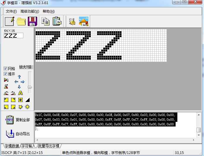
pictures
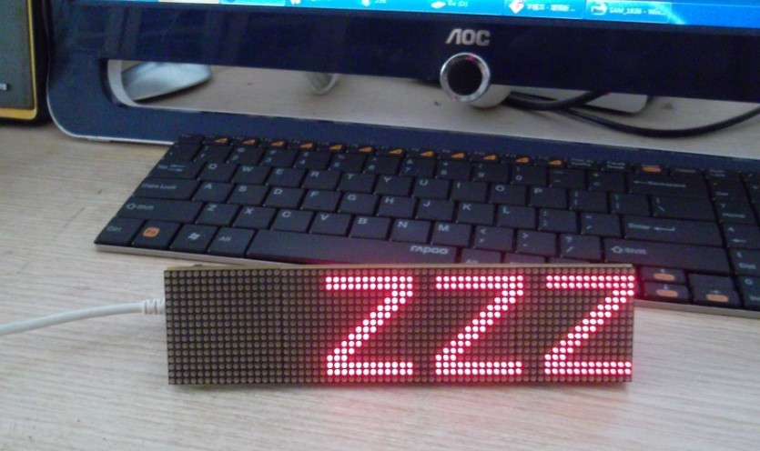
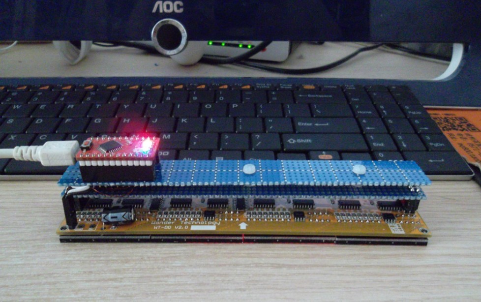
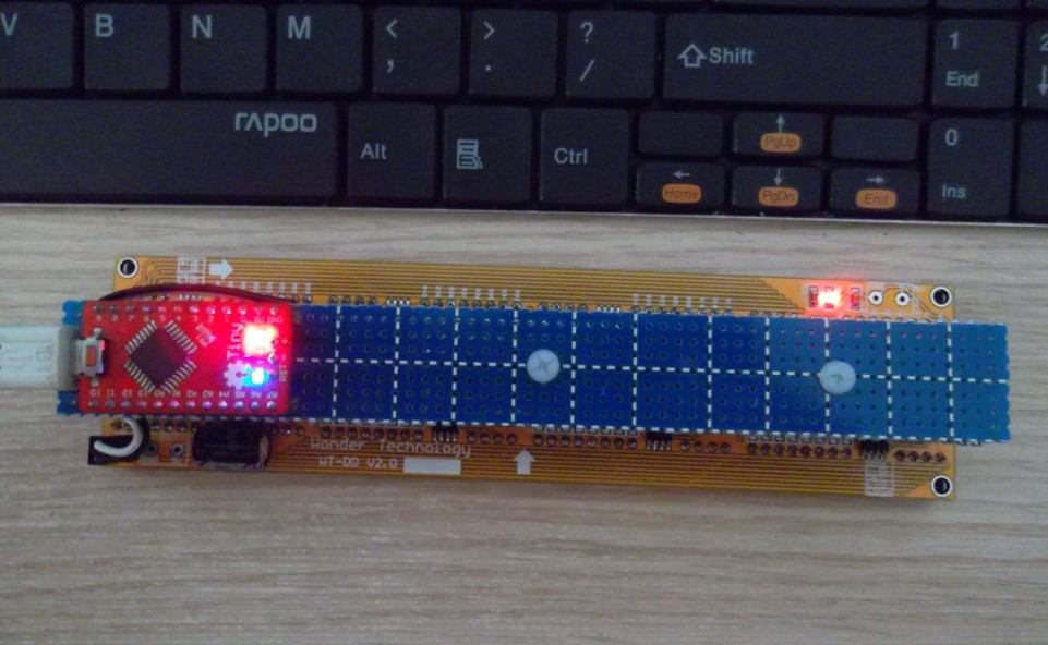
Following figure shows . master Arduino Tiny.welcome to finish according to this interesting Ardunio lattice display screen work. I hope this article can give you broaden the thinking of some .
Leave a Reply
You must be logged in to post a comment.