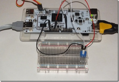
[vc_row][vc_column width=”1/1″][vc_column_text]This tutorial will show you how to program the pcDuino to read an analog input.
It assumes you have a basic working knowledge of the pcDuino on Linux. It builds upon the pcDuino – Blink Tutorial.[/vc_column_text][/vc_column][/vc_row][vc_row][vc_column width=”1/1″][vc_tour][vc_tab title=”Hardware Set Up” tab_id=”1389075265-1-7″][vc_column_text]For this tutorial you will need the following items:
- A pcDuino running the 20130531 Ubuntu image with ssh.
- A breadboard.
- A potentiometer.
- Three wire jumpers.
- The source code below for analog.c
Hardware Setup
A potentiometer also known as a pot has three terminals. These terminals connect to the the input voltage, the input channel and ground. The input channel terminal is connected inside the pot to a wiper that moves across resistive material in the pot. The closer it is to the terminal with ground connected the lower the voltage and the closer it is to the terminal with the input voltage higher the voltage is.
I used a 10K Ohm breadboard compatible potentiometer similar to the one in the picture below.

From left to right on the breadboard in the picture above are connected: ground, ADC2, and 3.3V.
At this point you are ready to power up your pcDuino.[/vc_column_text][/vc_tab][vc_tab title=”Analog Read Program” tab_id=”1389075265-2-95″][vc_column_text]Analog Read Program
To read an analog pin you just need to open a special file and then read the file.
The file is /proc/adc# where the # is replaced with 0 – 5 depending on the pin you are using. ADC0 and ADC1 work with voltages from 0V to 2V and have 6 bits. This means that you are going to be reading values from 0 to 63. ADC1 – ADC5 work with voltages from 0V to 3.3V and have 12 bits which means you will read values from 0 – 4095.
When /proc/adc# is read it returns the following string: adc#:<value> where # is the adc pin 0 to 5 and value is 0 to 63 for ADC0 and ADC1 and 0 to 4095 for ADC2 to ADC5.
Download the code here: analog
Program Setup
Using the editor of your choice or the command “cat > analog.c” you will need to get the program on to your pcDuino. See the Blink Tutorial for screen shots on how to do this.
Next you will need to load the appropriate driver if it isn’t already loaded when you boot your system. You can check using the lsmod command and then load the driver using “sudo modprobe adc” again there are screenshots of this in the Blink Tutorial.
Next compile your program using “gcc analog.c –o analog” and then run it using “./analog”. You should get a series of numbers printed on your screen. These numbers should change when you rotate the pot attached to the pcDuino.
Acknowledgements
Thanks to the folks at Sparkfun and their great Getting Started with pcDuino for getting me started with putting this tutorial together. Also thanks to the folks on the pcDuino website for their support. Check out the website and forums for more information.
Source: http://digitalhacksblog.blogspot.com/2013/09/pcduino-analog-read-tutorial.html[/vc_column_text][/vc_tab][/vc_tour][/vc_column][/vc_row]


October 9, 2014 at 5:16 am
Why is the standard ADC value high i.e. 4095 ? Has there been some reversed logic introduced?