[vc_row][vc_column width=”1/1″][vc_column_text]Mamba-Narrow Band Powerline Communication Shield of LinkSprite is PLM1 chip modem chip as the core of digital modulation communication module, which uses half-duplex communication, the routine’s perspective of open source introduce Mamba applications on pcduino . Experiments with direct-connect mode, and not connected to the grid, but this does not affect the use and learning of experimental modules.[/vc_column_text][vc_tour][vc_tab title=”Parts List” tab_id=”1389057779-1-8″][vc_column_text]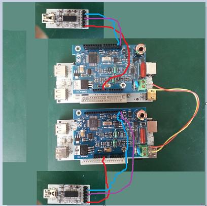 [/vc_column_text][/vc_tab][vc_tab title=”Test Code” tab_id=”1389057779-2-50″][vc_column_text]
The complete sample code can be (mamba_pcduino) to download here.
The main program as follows:
/****************************************************************************************** * Sample code for plm1 library. * * * * Project description: * This program acts as a bridge from RS-232 to Powerline and Powerline * to RS-232. It features a simple main loop and 4 ISR; 2 for the UART * one for the PLM-1 external interrupt and one for a 10 ms timer. * * The interrupt for the PLM-1 external interrupt is mandatory. This * ISR handles the interrupts required for transmission and reception. * The higher the configuration of the PLM-1 baud rate, the faster * the interrupts will occur. * * Project files: * plm1.h Declarations of the plm1 library functions and definitions of user * parameters for the configuration of plm1. * plmcfg.h Contains definitions of reference configuration strings for the PLM-1. * ports.h Definitions of macros used for I/O manipulation. * serial.h Declarations of functions used for serial communication. * spi.h Enumerations and macros used for SPI communication with the PLM-1. * * main.c Main function and interrupt handlers of the program. * plm.c Libplm library. Contains all functions used by the library and the * SPI initialization function for use with the PLM-1. * serial.c Functions used for serial communication. ******************************************************************************************/ #include <stdio.h> #include <stdbool.h> #include <string.h> #include <core.h> #include "spi.h" #include "plm1.h" #define ledpin 6 #define MOSI 11 #define MISO 12 #define SCK 13 /* Timer 0 Configuration */ #define TIMER0_CLOCK_SRC_HZ ( F_CPU / 1024 ) /* Nb ticks per second = 6144000 / 1024 = 6000 */ //15626 #define TIMER0_NB_INT_FOR_100_MS 10 //10 /* Nb ticks per 100ms = 600 */ #define TIMER0_NB_TICKS_FOR_100_MS 156 //60 /* Nb ticks per 100ms = (10 * 60) */ #define TIMER0_RESET_VALUE (255 - TIMER0_NB_TICKS_FOR_100_MS) static volatile bool uart_tx_flag = false; /* Flag for Tx UART interrupt. */ static volatile bool uart_rx_flag = false; /* Flag for Rx UART interrupt. */ static volatile bool timer_flag = false; /* Flag for Timer interrupt. */ static uint8_t uart_rx_data; /* Rx UART data read. */ uint8_t rx_packet[PLM_RX_MAX_PACKET_SIZE]; uint8_t rx_length = 0; uint8_t tx_packet[PLM_TX_MAX_PACKET_SIZE]; uint8_t tx_length = 0; uint32_t timecount4,timecount; extern char e; bool time_e; void delay_us(int t) { int i; int j; for(j=0;j<t;j++) for(i=0;i<1000;i++); } void setup() { pinMode(MOSI,OUTPUT); pinMode(SCK,OUTPUT); pinMode(nPLM_RESET,OUTPUT); pinMode(PLM_CS,OUTPUT); pinMode(MISO,INPUT); pinMode(ledpin,OUTPUT); serial_init(); spi_init( SPI_SPEED_F16 ); /* Initialization of plm1 library. */ digitalWrite(ledpin, LOW); plm1_init();//send_next_nibble /* Initialization of the serial communication. */ digitalWrite(ledpin, HIGH); attachInterrupt(0,SIGNAL,RISING); /* Activate external interrupt 0 for PLM-1 */ //Serial.print(5); } void loop(void) { if((timecount>100)&&(time_e)) { time_e=false; timecount4=0; timer_flag=true; timecount=0; } else if(time_e) { if(timecount4>50) { timecount4=0; timecount++; } else timecount4++; } if (Serial.available()) { uart_rx_data = Serial.read(); //Serial.write(uart_rx_data); uart_rx_flag = true; } if(uart_tx_flag) { uart_tx_flag = false; serial_tx_buffer_empty(); } /* Flag true if a Rx UART interrupt occured. */ if(uart_rx_flag) { /* Flag active if interrupt UART Rx Data Available was reaised. * When serial data is received, a 10 ms timer is started. * If the timer expires before additional data is received from the * UART, a transmission is started. */ uart_rx_flag = false; timer_flag = false; timecount4=0; timecount=0; //&&(time_e) /* Disable timer interrupt. */ //TIMSK0 = 0x00; /* Fill the buffer with data from UART. */ tx_packet[tx_length++] = uart_rx_data; /* Start the 10ms timer. If the timer interrupt occurs before the next data byte, * send the packet. Otherwise, the timer is reset. */ if(tx_length < PLM_TX_MAX_PACKET_SIZE - 10) { time_e=true; //TCNT0 = 0x00; /* Reset timer. */ //TIMSK0 = _BV(OCIE0A); /* Enable Compare Match A interrupt. */ } /* If the packet size is getting near the maximum, start immediately the transmission. */ else { time_e=false; /* plm1_send_data returns true if the library has queued the packet sucessfully. */ if(plm1_send_data(tx_packet, tx_length))// { /* Reset tx buffer if the packet was successfully transferred to the PLM-1 library. */ tx_length = 0; } // else // { // TCNT0 = 0x00; // TIMSK0 = _BV(OCIE0A); // } } } /* Flag tue if a timer interrupt occured. */ if(timer_flag) { timer_flag = false; //Serial.write(0xdd); /* plm1_send_data returns true if the library has queued the packet sucessfully. */ if( plm1_send_data(tx_packet, tx_length) ) { //Serial.write(tx_length); tx_length = 0; //TIMSK0 = 0x00; /* Disable timer interrupt. */ } } /* When a packet is received, plm1_receive returns the length of the * packet and copies the contents of the packet in rx_packet. */ if( (rx_length = plm1_receive(rx_packet)) ) { output_serial_data(rx_packet, rx_length); //plm.rx.write_next=0; //plm.rx.read_next=0; //plm.rx.pkt_end=0; } // } // return 0; /* The main() function will never return. */ } /* Interrupt Service Routine provenant de la ligne d'interruption du PLM. */ void SIGNAL(void) { plm1_interrupt(); } /* 10 ms timer interrupt ISR. */ //SIGNAL(TIMER0_COMPA_vect) //{ //Serial.write(0x33); // timer_flag = true; //} // Uart RX //********************************************* /*SIGNAL(USART_RX_vect) { uart_rx_flag = true; uart_rx_data = UDR0; }*/ /* USART Tx Buffer Empty ISR. */ /*SIGNAL(USART_UDRE_vect) { uart_tx_flag = true; }*/ |
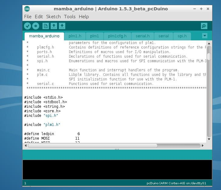
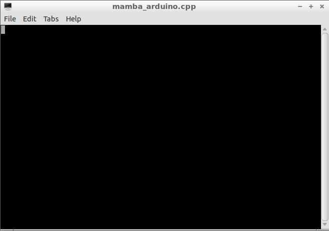
[/vc_column_text][/vc_tab][vc_tab title=”Running” tab_id=”1389058602690-2-6″][vc_column_text]Usb cable connect into the computer and power of each module,then let pcduino connect to the monitor,open the arduino IDE when the system starts, open the program.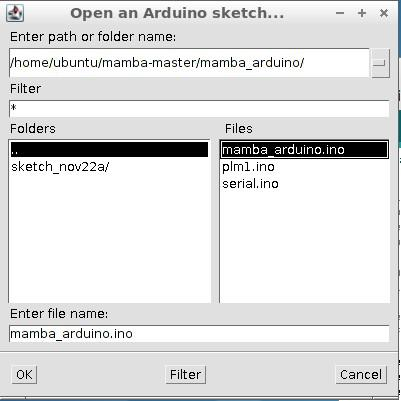
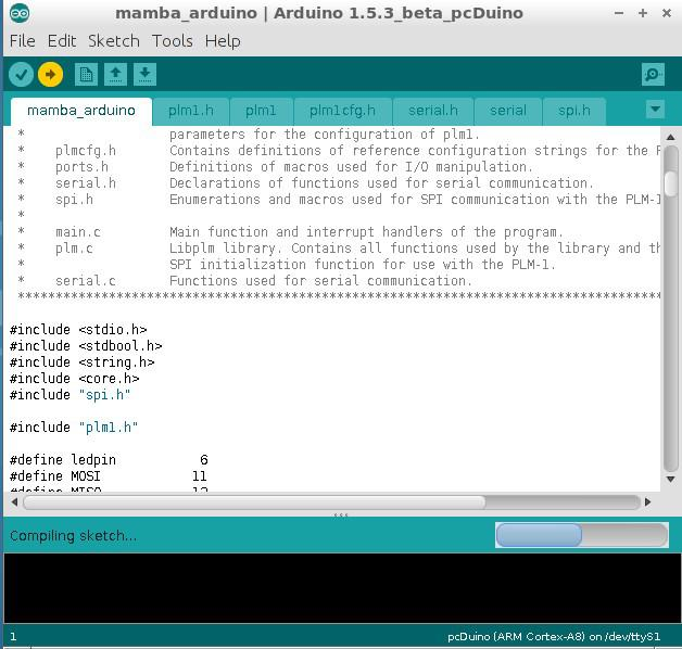
Click the Download button to download the program,it will running automatically
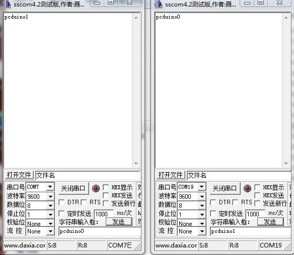
 [/vc_column_text][/vc_tab][vc_tab title=”Results” tab_id=”1389059002059-3-9″][vc_column_text]Open the serial port tools, you can use the familiar tools, communication effect as follows
 [/vc_column_text][/vc_tab][/vc_tour][/vc_column][/vc_row]
Leave a Reply
You must be logged in to post a comment.