[vc_row][vc_column width=”1/1″][vc_column_text]There are two flavors to use C langue on pcDuino, one is to use command line ‘make’ style. The other one is to use Arduino style IDE. The Arduino IDE is included in version 20130531.
Toolchain of the Arduino library
The source code could be compiled with GCC tool chain. The GCC is pre-installed on the board. You could enter gcc in Ubuntu terminal under any directory.
Cautious: you may need a bridge board to work with 5V Arduino Shield
All IO on the pcDuino board are 3.3V IO.
If the Arduino shield needs 5V input or 5V output, you need a bridge board for pcDuino. Otherwise, you may damage your pcDuino board if you directly connect your shield with the pcDuino.[/vc_column_text][/vc_column][/vc_row][vc_row][vc_column width=”1/1″][vc_tour][vc_tab title=”Command line style” tab_id=”1389171815-1-64″][vc_column_text]The quickest way to get going with Arduino sketches is to start with the samples so you have a ‘template’ to guide you.
For parts of this guide to work, you’re pcDuino needs to be connected to the internet and you also need a terminal session running on the pcDuino.
Setup (one time)
If not already done, set up git. Do this using the command:
ubuntu@ubuntu:~$ sudo apt-get install git
Make sure you’re in your home folder by typing
ubuntu@ubuntu:~$ cd
ubuntu@ubuntu:~$ pwd
/home/Ubuntu
Now download the distribution from github by typing
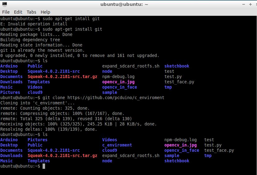
ubuntu@ubuntu:~$ git clone https://github.com/pcduino/c_enviroment
Cloning into ‘c_enviroment’…
remote: Counting objects: 250, done.
remote: Compressing objects: 100% (166/166), done.
remote: Total 250 (delta 87), reused 232 (delta 69)
Receiving objects: 100% (250/250), 302.59 KiB | 78 KiB/s, done.
Resolving deltas: 100% (87/87), done.
You should now have a folder called c_enviroment. You can check by typing ls:
ubuntu@ubuntu:~$ ls
Desktop Documents Downloads Music Pictures Public Templates Videos arduino c_enviroment sa
Initial Look Around
Change into the c_envoroment folder:
ubuntu@ubuntu:~$ cd c_enviroment
ubuntu@ubuntu:~/c_enviroment$ ls
Makefile hardware libraries output sample
Now run make to make the libraries and the examples with the following command:
ubuntu@ubuntu:~/c_enviroment$ make
You should see a series of compile commands occurring without errors with the last line being:
make[1]: Leaving directory `/home/ubuntu/c_enviroment/sample’
The resulting binary files are found in the output/test folder
ubuntu@ubuntu:~/c_enviroment$ cd output/test
ubuntu@ubuntu:~/c_enviroment/output/test$ ll
total 660
drwxrwxr-x 2 ubuntu ubuntu 4096 Apr 27 06:59 ./
drwxrwxr-x 3 ubuntu ubuntu 4096 Apr 27 06:49 ../
-rwxrwxr-x 1 ubuntu ubuntu 13868 Apr 27 06:58 adc_test*
-rwxrwxr-x 1 ubuntu ubuntu 28284 Apr 27 06:58 adxl345_test*
-rwxrwxr-x 1 ubuntu ubuntu 14209 Apr 27 06:58 interrupt_test*
-rwxrwxr-x 1 ubuntu ubuntu 13726 Apr 27 06:58 io_test*
-rwxrwxr-x 1 ubuntu ubuntu 13712 Apr 27 06:59 linker_button_test*
-rwxrwxr-x 1 ubuntu ubuntu 13907 Apr 27 06:59 linker_buzzer_test*
-rwxrwxr-x 1 ubuntu ubuntu 13689 Apr 27 06:59 linker_hall_sensor_test*
-rwxrwxr-x 1 ubuntu ubuntu 13760 Apr 27 06:59 linker_joystick_test*
-rwxrwxr-x 1 ubuntu ubuntu 13769 Apr 27 06:59 linker_led_bar_test*
-rwxrwxr-x 1 ubuntu ubuntu 13690 Apr 27 06:59 linker_led_test*
-rwxrwxr-x 1 ubuntu ubuntu 14290 Apr 27 06:59 linker_light_sensor_test*
-rwxrwxr-x 1 ubuntu ubuntu 13696 Apr 27 06:59 linker_magnetic_sensor_test*
-rwxrwxr-x 1 ubuntu ubuntu 14175 Apr 27 06:59 linker_potentiometer_test*
-rwxrwxr-x 1 ubuntu ubuntu 13658 Apr 27 06:59 linker_relay_test*
-rwxrwxr-x 1 ubuntu ubuntu 28530 Apr 27 06:59 linker_rtc_test*
-rwxrwxr-x 1 ubuntu ubuntu 14136 Apr 27 06:59 linker_sound_sensor_test*
-rwxrwxr-x 1 ubuntu ubuntu 13832 Apr 27 06:59 linker_temperature_sensor_test*
-rwxrwxr-x 1 ubuntu ubuntu 13714 Apr 27 06:59 linker_tilt_test*
-rwxrwxr-x 1 ubuntu ubuntu 13689 Apr 27 06:59 linker_touch_sensor_test*
-rwxrwxr-x 1 ubuntu ubuntu 40523 Apr 27 06:58 liquidcrystal_i2c*
-rwxrwxr-x 1 ubuntu ubuntu 40523 Apr 27 06:58 liquidcrystal_spi*
-rwxrwxr-x 1 ubuntu ubuntu 38242 Apr 27 06:59 pn532_readAllMemoryBlocks*
-rwxrwxr-x 1 ubuntu ubuntu 38238 Apr 27 06:59 pn532readMifareMemory*
-rwxrwxr-x 1 ubuntu ubuntu 38240 Apr 27 06:59 pn532readMifareTargetID*
-rwxrwxr-x 1 ubuntu ubuntu 38263 Apr 27 06:59 pn532writeMifareMemory*
-rwxrwxr-x 1 ubuntu ubuntu 13842 Apr 27 06:58 pwm_test*
-rwxrwxr-x 1 ubuntu ubuntu 32336 Apr 27 06:58 serial_test*
-rwxrwxr-x 1 ubuntu ubuntu 14449 Apr 27 06:58 spi_test*
-rwxrwxr-x 1 ubuntu ubuntu 18822 Apr 27 06:59 tone_test*
The source for each one is in the sample folder.
ubuntu@ubuntu:~/c_enviroment/output/test$ cd ../../sample
ubuntu@ubuntu:~/c_enviroment/sample$ ll
total 148
drwxrwxr-x 2 ubuntu ubuntu 4096 Apr 27 06:49 ./
drwxr-xr-x 7 ubuntu ubuntu 4096 Apr 27 06:58 ../
-rw-rw-r– 1 ubuntu ubuntu 1368 Apr 27 06:49 Makefile
-rw-rw-r– 1 ubuntu ubuntu 467 Apr 27 06:49 adc_test.c
-rw-rw-r– 1 ubuntu ubuntu 6589 Apr 27 06:49 adx.c
-rw-rw-r– 1 ubuntu ubuntu 5416 Apr 27 06:49 adxl345_test.c
-rw-rw-r– 1 ubuntu ubuntu 92 Apr 27 06:49 core.h
-rw-rw-r– 1 ubuntu ubuntu 830 Apr 27 06:49 interrupt_test.c
-rw-rw-r– 1 ubuntu ubuntu 781 Apr 27 06:49 io_test.c
-rw-rw-r– 1 ubuntu ubuntu 430 Apr 27 06:49 linker_button_test.c
-rw-rw-r– 1 ubuntu ubuntu 1420 Apr 27 06:49 linker_buzzer_test.c
-rw-rw-r– 1 ubuntu ubuntu 390 Apr 27 06:49 linker_hall_sensor_test.c
-rw-rw-r– 1 ubuntu ubuntu 327 Apr 27 06:49 linker_joystick_test.c
-rw-rw-r– 1 ubuntu ubuntu 2202 Apr 27 06:49 linker_led_bar_test.c
-rw-rw-r– 1 ubuntu ubuntu 613 Apr 27 06:49 linker_led_test.c
-rw-rw-r– 1 ubuntu ubuntu 1197 Apr 27 06:49 linker_light_sensor_test.c
-rw-rw-r– 1 ubuntu ubuntu 404 Apr 27 06:49 linker_magnetic_sensor_test.c
-rw-rw-r– 1 ubuntu ubuntu 647 Apr 27 06:49 linker_potentiometer_test.c
-rw-rw-r– 1 ubuntu ubuntu 331 Apr 27 06:49 linker_relay_test.c
-rw-rw-r– 1 ubuntu ubuntu 2505 Apr 27 06:49 linker_rtc_test.c
-rw-rw-r– 1 ubuntu ubuntu 646 Apr 27 06:49 linker_sound_sensor_test.c
-rw-rw-r– 1 ubuntu ubuntu 1145 Apr 27 06:49 linker_temperature_sensor_test.c
-rw-rw-r– 1 ubuntu ubuntu 405 Apr 27 06:49 linker_tilt_test.c
-rw-rw-r– 1 ubuntu ubuntu 389 Apr 27 06:49 linker_touch_sensor_test.c
-rw-rw-r– 1 ubuntu ubuntu 797 Apr 27 06:49 liquidcrystal_i2c.c
-rw-rw-r– 1 ubuntu ubuntu 831 Apr 27 06:49 liquidcrystal_spi.c
-rw-rw-r– 1 ubuntu ubuntu 2002 Apr 27 06:49 pitches.h
-rw-rw-r– 1 ubuntu ubuntu 3149 Apr 27 06:49 pn532_readAllMemoryBlocks.c
-rw-rw-r– 1 ubuntu ubuntu 1690 Apr 27 06:49 pn532readMifareMemory.c
-rw-rw-r– 1 ubuntu ubuntu 1117 Apr 27 06:49 pn532readMifareTargetID.c
-rw-rw-r– 1 ubuntu ubuntu 2326 Apr 27 06:49 pn532writeMifareMemory.c
-rw-rw-r– 1 ubuntu ubuntu 498 Apr 27 06:49 pwm_test.c
-rw-rw-r– 1 ubuntu ubuntu 2079 Apr 27 06:49 serial_test.c
-rw-rw-r– 1 ubuntu ubuntu 785 Apr 27 06:49 spi_test.c
To view the contents of a sample sketch, (this example we’ll look at the contents of linker_led_test.c) type:
ubuntu@ubuntu:~/c_enviroment/sample$ cat linker_led_test.c
/*
* LED test program
*/
#include <core.h>
int led_pin = 1;
void setup()
{
if(argc != 2){
goto _help;
}
led_pin = atoi(argv[1]);
if((led_pin < 0) || (led_pin > 13)){
goto _help;
}
pinMode(led_pin, OUTPUT);
return;
_help:
printf(“Usage %s LED_PIN_NUM(0-13)n”, argv[0]);
exit(-1);
}
void loop()
{
digitalWrite(led_pin, HIGH); // set the LED on
delay(1000); // wait for a second
digitalWrite(led_pin, LOW); // set the LED off
delay(1000); // wait for a second
}
Editing an Existing Sketch
You will probably want to change some of these samples as an initial play so will need a text editor. We tend to use nano, but you may already have a favourite. If not, install nano by typing:
ubuntu@ubuntu:~/c_enviroment/sample$ sudo apt-get install nano
You should see nano being downloaded and installed.
Let’s use the same sketch as the example, type:
ubuntu@ubuntu:~/c_enviroment/sample$ nano linker_led_test.c
You should see something like:
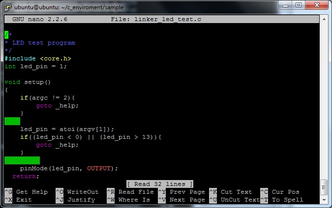
One thing you may notice with this sketch, it compiles to the command line. This example shows how you can pass parameters to the sketch when calling it from the command line. This is optional as you will see in some of the other sketches, but does add some benefit to writing sketches to run on the pcDuino.
Creating Your Own Sketch
Now lets create our own sketch and work out how to compile it so it runs. It will be a button on pin 7 that when pressed, turns on an LED on pin 8.
While in the sample folder, type:
ubuntu@ubuntu:~/c_enviroment/sample$ nano button_led.c
An empty nano screen should appear.
Copy and paste the following code into it. (Remember to paste in nano at the cursor, just right click the mouse button).
#include <core.h> // Required first line to run on pcDuino
int ledPin = 8;
int buttonPin = 7;
// variables will change:
int buttonState = 0; // variable for reading the pushbutton status
void setup() {
// initialize the LED pin as an output:
pinMode(ledPin, OUTPUT);
// initialize the pushbutton pin as an input:
pinMode(buttonPin, INPUT);
}
void loop(){
// read the state of the pushbutton value:
buttonState = digitalRead(buttonPin);
// check if the pushbutton is pressed.
// if it is, the buttonState is HIGH:
if (buttonState == HIGH) {
// turn LED on:
digitalWrite(ledPin, HIGH);
}
else {
// turn LED off:
digitalWrite(ledPin, LOW);
}
}
Modify the Makefile and Compile
Now we need to add this new sketch to the Makefile in the samples folder. Open the Makefile with nano (or your favorite text editor).
ubuntu@ubuntu:~/c_enviroment/sample$ nano Makefile
You will see a section that lists all the OBJS something like:
OBJS = io_test adc_test pwm_test spi_test adxl345_test serial_test liquidcrystal_i2c liquidcrystal_spi interrupt_test tone_test
OBJS += linker_led_test linker_potentiometer_test linker_tilt_test linker_light_sensor_test linker_button_test
OBJS += linker_touch_sensor_test linker_magnetic_sensor_test linker_temperature_sensor_test linker_joystick_test
OBJS += linker_rtc_test linker_sound_sensor_test linker_buzzer_test linker_hall_sensor_test linker_led_bar_test linker_relay_test
OBJS += pn532_readAllMemoryBlocks pn532readMifareMemory pn532readMifareTargetID pn532writeMifareMemory
We’re going to add a line to the end of this with the name of the scketch we just created:
OBJS += button_led
Note, we don’t put the .c on the end.
Save the file and exit nano using <CTRL>X with a y and <enter>.
We now run make by typing:
ubuntu@ubuntu:~/c_enviroment/sample$ make
You should see a whole bunch of text with the end being:
button_led.c -o ../output/test/button_led ../libarduino.a
If all went well, you can go to the output/test folder and find your executable you have created:
ubuntu@ubuntu:~/c_enviroment/sample$ cd ../output/test/
ubuntu@ubuntu:~/c_enviroment/output/test$ ll
total 676
drwxrwxr-x 2 ubuntu ubuntu 4096 Apr 27 07:51 ./
drwxrwxr-x 3 ubuntu ubuntu 4096 Apr 27 06:49 ../
-rwxrwxr-x 1 ubuntu ubuntu 13868 Apr 27 07:51 adc_test*
-rwxrwxr-x 1 ubuntu ubuntu 28284 Apr 27 07:51 adxl345_test*
-rwxrwxr-x 1 ubuntu ubuntu 13668 Apr 27 07:51 button_led*
…..(not showing rest of listing here)
Run Your Sketch
To run it, once you have wired up a switch and led to the right pins, type:
ubuntu@ubuntu:~/c_enviroment/output/test$ ./button_led
To stop the program, <Ctrl>C
A Quick Re-Cap
- Add #include <core.h> to the top of your sketch.
- Create your sketch in the samples folder (if your familiar with linux, makefiles, and compiling code, you could set up your own)
- Add the filename to the Makefile in the samples folder in the OBJS section without the .c
- Run make
- Run the executable from the output/test folder.
- You can introduce command line arguments into your sketch to make it more transportable.
[/vc_column_text][/vc_tab][vc_tab title=”Arduino library and samples-UART” tab_id=”1389171815-2-65″][vc_column_text]UART
Reference:
Please refer to the Serial class from Arduino (http://arduino.cc/en/Reference/Serial).
Functions
- if (Serial)
- available()
- begin()
- end()
- find()
- findUntil()
- flush()
- parseFloat()
- parseInt()
- peek()
- print()
- println()
- read()
- readBytes()
- readBytesUntil()
- setTimeout()
- write()
- serialEvent()
UART Rx and Tx pins are shared with GPIO 0 and 1. Thus, if you are using UART, please don’t call pinMode to change function mode of GPIO 0 and 1.
Currently, the supported baud rates are: 300, 600, 1200, 2400, 4800, 9600, 19200, 38400, 57600 and 115200 Hz.
Sample
Accept the typing from the terminal, then print out the input in the second line. Both read and write operations are via UART interfaces.
Setup
Plugin USB-to-serial cable to PC USB port and install usb_to_serial driver to PC
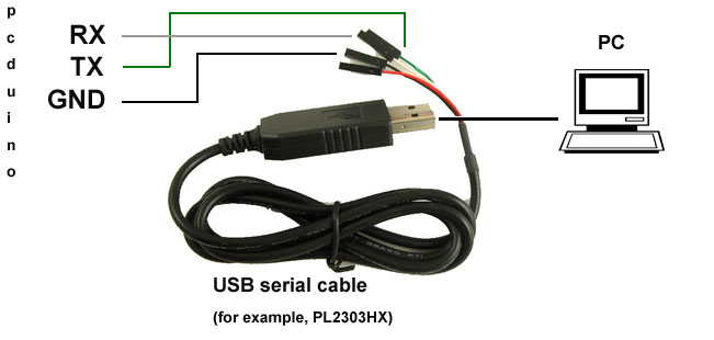
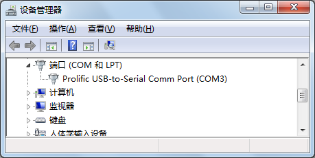
Check the windows computer device manager for com port device.
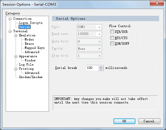
Run a terminal tool like “sercureCRT”, and configure the serial port parameters to 115200 8N1.
Then you can type on the terminal and see the output prints.
If you use Linux PC, you could use minicom tool for this sample.
Sample code
void setup() {
//Initialize serial with baudrate setting, the default config is SERIAL_8N1
int rate = 115200;
Serial.begin(rate);
//you will see the string on the terminal
Serial.println(“Serial begin: “);
}
void loop() {
//if you type the character in the terminal, available() will return the size you typed
if (Serial.available() > 0) {
// read the incoming byte:
char thisByte = Serial.read();
//print it on the terminal with DEC format
Serial.print(“I received: “);
Serial.println(thisByte, DEC);
}
delay(200);
}[/vc_column_text][/vc_tab][vc_tab title=”ADC” tab_id=”1389172815583-2-2″][vc_column_text]
ADC
Arduino functions
pcDuino has the internal reference voltage. For ADC0 and ADC1, the reference is 2V, for ADC2~5, the refernece is 3.3V. Thus, this function doesn’t change the reference voltage which is different from original Arduino board.
ADC0 and ADC1 are 6-bit ADC, the return value is from 0 ~ 63, ranging from 0V to 2V.
ADC2~ADC5 are 12-bit ADC, the return value is from 0 ~ 4095, means from 0V to 3.3V.
Notes:
- If you want to measure the high voltage, you can purchase the bridge board for pcDuino, it can measure max 5V input.
- For ADC0 and ADC1, though this function will return in 4us, the actual conversion rate is 250Hz. So if the input voltage changed, it can be detected in 4ms. For ADC2~ADC5, this function will return in 35us, the return value is the actual value measured.
Sample
Measure the dry battery’s voltage
Setup
Connect the battery’s N to any GND and P to the ADC1

Sample Code
Read the value of ADC
Int adc_id = 0;
void setup() {
//argv[1] store the adc id that will be measured.
//if no args, default adc_id is 0
if ( argc == 2 )
adc_id = atoi(argv[1]);
}
void loop() {
// get adc value
int value = analogRead(adc_id);
//delay some time in loop
delayMicroseconds(100000);
}[/vc_column_text][/vc_tab][vc_tab title=”PWM” tab_id=”1389173087215-3-1″][vc_column_text]Reference
– with value 0 to set the PWM IO to low level.
Notes:
1. PWM1 and PWM2 are hardware PWMs. They are set to 520Hz with 256 duty cycle level by default. PWM1/3/4/5[AJ1] are 5Hz with 10 duty cycle level by default. Thus, the actual duty level is value*10/256. PWM1/3/4/5[AJ2] are simulated by GPIO in software, so they couldn’t set high frequency. If you need simulate high frequency and accurate PWM with software GPIO, the CPU will be in very high use.
2. The six PWM pins are shared with GPIO, and PWM4/PWM5 pins are also shared with SPI IO. So if you are using PWM, don’t call pinMode() or SPI function to specific IO.
Functions not implemented
tone()
noTone()
tone function can generate a square wave with the setting frequency and duration.
You can’t use tone function to play the ringtones as Arduino does, because pcDuino’s tone function can work under just several frequency setting. We will improve this in future release.
An extend function will be provided for those who needs higher or lower frequency PWM. So far, we couldn’t support 256 duty cycle level in every frequency. Assume the max duty cycle in this frequency is max_level, the actual level will be level * max_level/256. This function is also useful for tone() function.
PWM1/3/4/5 will be improved in future release. The ultimate goal is to provide 500Hz support with 256 duty cycle.
Sample
Use PWM to control buzzer to make sound in different frequency
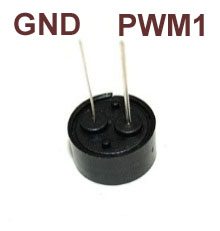
Setup
A buzzer connect to PWM1
Sample code
int pwm_id = 1;
int duty_level = 128;
void setup() {
//set the default freq (#define default_freq 0)
//PWM0/3/4/5, default_freq is 5Hz, and PWM1/2 is 520Hz
if ( argc > 1 )
pwm_id = atoi(argv[1]);
if ( argc > 2 ) //duty level can be 0 ~ 256
duty_level = argv[2];
//start the PWM
analogWrite(pwm_id, duty_level);
}
void loop() {
//delay in loop
delay(10);
}[/vc_column_text][/vc_tab][vc_tab title=”GPIO” tab_id=”1389173164686-4-3″][vc_column_text]Reference functions
- pinMode()
- digitalRead()
- digitalWrite()
- pulseIn()
Sample
Turn on or off LED by pressing and releasing the button connected to the GPIO
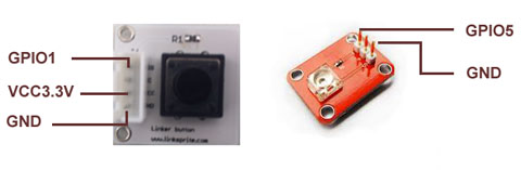
Setup
Connect the shield to the GPIO1 and connect the LED to GPIO5
Sample code
int led_pin = 5;
int btn_pin = 1;
void setup() {
if ( argc == 3 ) {
btn_pin = atoi(argv[1]);
led_pin = atoi(argv[2]);
}
//set the gpio to input or output mode
pinMode(led_pin, OUTPUT);
pinMode(btn_pin, INPUT);
}
void loop() {
//press btn_pin to turn on LED
int value = digitalRead(btn_pin);
if ( value == HIGH ) { // button pressed
digitalWrite(led_pin, HIGH); // turn on LED
} else { // button released
digitalWrite(led_pin, LOW); // turn off LED
}
delay(100);
}[/vc_column_text][/vc_tab][vc_tab title=”I2C” tab_id=”1389173267295-5-0″][vc_column_text]Reference function
Please refer to the Wire class (http://arduino.cc/en/Reference/Wire)
Functions
- begin()
- requestFrom()
- beginTransmission()
- endTransmission()
- write()
- available()
- read()
- onReceive()
- onRequest()
pcDuino I2C is set 200KHz, 7-bit version, master only by default
Future improvements:
Function will be provided to users to allow them to configure the I2C frequency. And we will also support 10-bit mode.
Sample
Read the X, Y and Z coordinates for triple axis via I2C interface
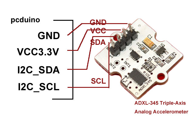
Setup
Connect the I2C port of Triple-Axis with pcDuino
Code:
#include <Wire.h>
#include <ADXL345.h>
ADXL345 adxl; //variable adxl is an instance of the ADXL345 library
void setup(){
Serial.begin(9600);
adxl.powerOn();
//set activity/ inactivity thresholds (0-255)
adxl.setActivityThreshold(75); //62.5mg per increment
adxl.setInactivityThreshold(75); //62.5mg per increment
adxl.setTimeInactivity(10); // how many seconds of no activity is inactive?
//look of activity movement on this axes – 1 == on; 0 == off
adxl.setActivityX(1);
adxl.setActivityY(1);
adxl.setActivityZ(1);
//look of inactivity movement on this axes – 1 == on; 0 == off
adxl.setInactivityX(1);
adxl.setInactivityY(1);
adxl.setInactivityZ(1);
//look of tap movement on this axes – 1 == on; 0 == off
adxl.setTapDetectionOnX(0);
adxl.setTapDetectionOnY(0);
adxl.setTapDetectionOnZ(1);
//set values for what is a tap, and what is a double tap (0-255)
adxl.setTapThreshold(50); //62.5mg per increment
adxl.setTapDuration(15); //625us per increment
adxl.setDoubleTapLatency(80); //1.25ms per increment
adxl.setDoubleTapWindow(200); //1.25ms per increment
//set values for what is considered freefall (0-255)
adxl.setFreeFallThreshold(7); //(5 – 9) recommended – 62.5mg per increment
adxl.setFreeFallDuration(45); //(20 – 70) recommended – 5ms per increment
//setting all interrupts to take place on int pin 1
//I had issues with int pin 2, was unable to reset it
adxl.setInterruptMapping( ADXL345_INT_SINGLE_TAP_BIT, ADXL345_INT1_PIN );
adxl.setInterruptMapping( ADXL345_INT_DOUBLE_TAP_BIT, ADXL345_INT1_PIN );
adxl.setInterruptMapping( ADXL345_INT_FREE_FALL_BIT, ADXL345_INT1_PIN );
adxl.setInterruptMapping( ADXL345_INT_ACTIVITY_BIT, ADXL345_INT1_PIN );
adxl.setInterruptMapping( ADXL345_INT_INACTIVITY_BIT, ADXL345_INT1_PIN );
//register interrupt actions – 1 == on; 0 == off
adxl.setInterrupt( ADXL345_INT_SINGLE_TAP_BIT, 1);
adxl.setInterrupt( ADXL345_INT_DOUBLE_TAP_BIT, 1);
adxl.setInterrupt( ADXL345_INT_FREE_FALL_BIT, 1);
adxl.setInterrupt( ADXL345_INT_ACTIVITY_BIT, 1);
adxl.setInterrupt( ADXL345_INT_INACTIVITY_BIT, 1);
}
void loop(){
//Boring accelerometer stuff
int x,y,z;
adxl.readXYZ(&x, &y, &z); //read the accelerometer values and store them in variables x,y,z
// Output x,y,z values
Serial.print(“values of X , Y , Z: “);
Serial.print(x);
Serial.print(” , “);
Serial.print(y);
Serial.print(” , “);
Serial.println(z);
double xyz[3];
double ax,ay,az;
adxl.getAcceleration(xyz);
ax = xyz[0];
ay = xyz[1];
az = xyz[2];
Serial.print(“X=”);
Serial.print(ax);
Serial.println(” g”);
Serial.print(“Y=”);
Serial.print(ay);
Serial.println(” g”);
Serial.print(“Z=”);
Serial.println(az);
Serial.println(” g”);
Serial.println(“**********************”);
delay(500);
/*
//Fun Stuff!
//read interrupts source and look for triggerd actions
//getInterruptSource clears all triggered actions after returning value
//so do not call again until you need to recheck for triggered actions
byte interrupts = adxl.getInterruptSource();
// freefall
if(adxl.triggered(interrupts, ADXL345_FREE_FALL)){
Serial.println(“freefall”);
//add code here to do when freefall is sensed
}
//inactivity
if(adxl.triggered(interrupts, ADXL345_INACTIVITY)){
Serial.println(“inactivity”);
//add code here to do when inactivity is sensed
}
//activity
if(adxl.triggered(interrupts, ADXL345_ACTIVITY)){
Serial.println(“activity”);
//add code here to do when activity is sensed
}
//double tap
if(adxl.triggered(interrupts, ADXL345_DOUBLE_TAP)){
Serial.println(“double tap”);
//add code here to do when a 2X tap is sensed
}
//tap
if(adxl.triggered(interrupts, ADXL345_SINGLE_TAP)){
Serial.println(“tap”);
//add code here to do when a tap is sensed
} */
}[/vc_column_text][/vc_tab][vc_tab title=”SPI” tab_id=”1389238030061-6-4″][vc_column_text]Reference functions
Please refer to the SPI class. (http://arduino.cc/en/Reference/SPI)
Functions
- begin()
- end()
- setBitOrder()
- setClockDivider()
- setDataMode()
- transfer()
pcDuino SPI only works in master mode. The max speed is 12MHz. Clock divider can be 2/4/8/16/32/64/128.
Note that calling the setClockDivider() function just saves the setting of clock divider but without the real clock change. It works when the transfer function called.
Sample
To read an SPI flash ID of M25P16
Setup
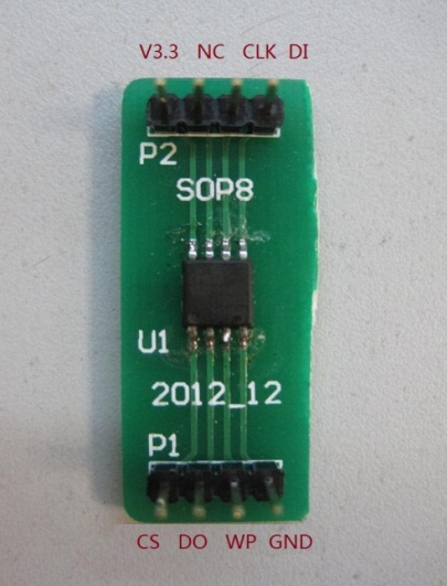
GND ———- GND
V3.3 ———- 3.3V
DO ———- SPI_MISO
DI ———- SPI_MOSI
CS ———- SPI_CS
CLK ——— SPI_CLK
Sample code
int ReadSpiflashID(void) {
char CMD_RDID = 0x9f;
char id[3];
int flashid = 0;
memset(id, 0x0, sizeof(id));
id[0] = SPI.transfer(CMD_RDID, SPI_CONTINUE);
id[1] = SPI.transfer(0x00, SPI_CONTINUE);
id[2] = SPI.transfer(0x00, SPI_LAST);
//MSB first
flashid = id[0] << 8;
flashid |= id[1];
flashid = flashid << 8;
flashid |= id[2];
return flashid;
}
void setup() {
// initialize SPI:
SPI.begin();
}
void loop() {
//MSB first
printf(“spi flash id = 0x%x\n”, ReadSpiflashID());
delay(2000);
}
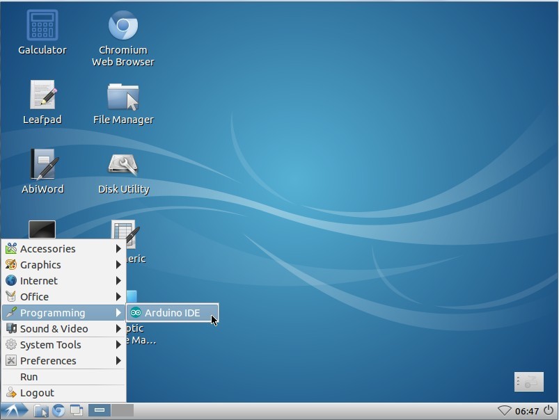
[/vc_column_text][/vc_tab][vc_tab title=”Arduino IDE” tab_id=”1389238398322-7-7″][vc_column_text]pcDuino Image 20130531 has Arduino IDE built-in.
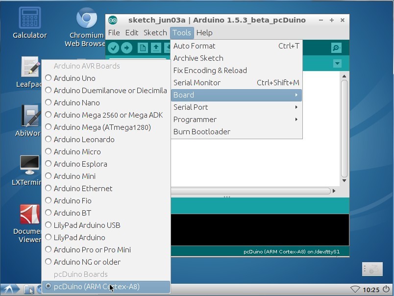
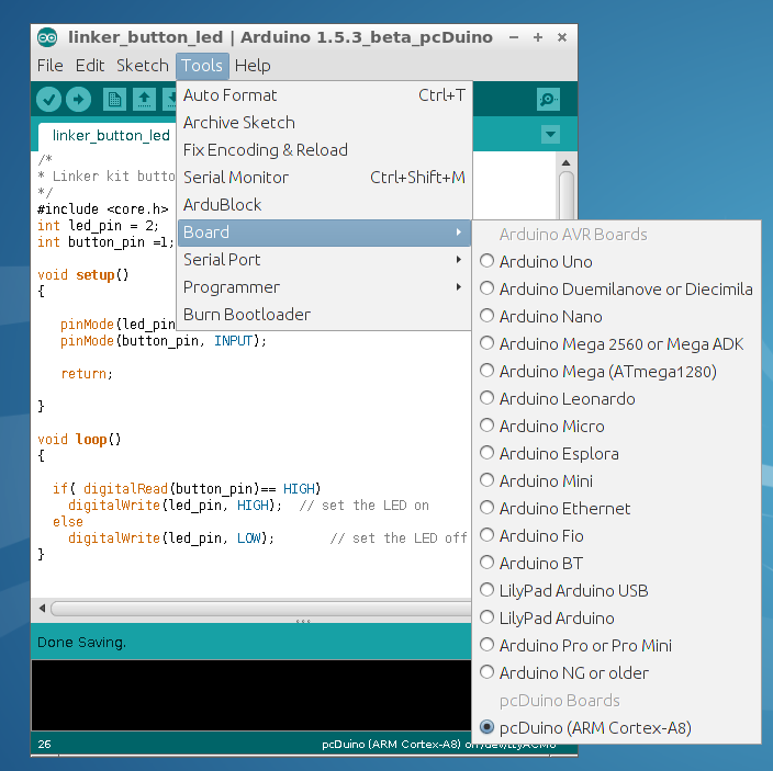
We added a new board type ‘pcDuino’. By default, the board type is pcDuino.
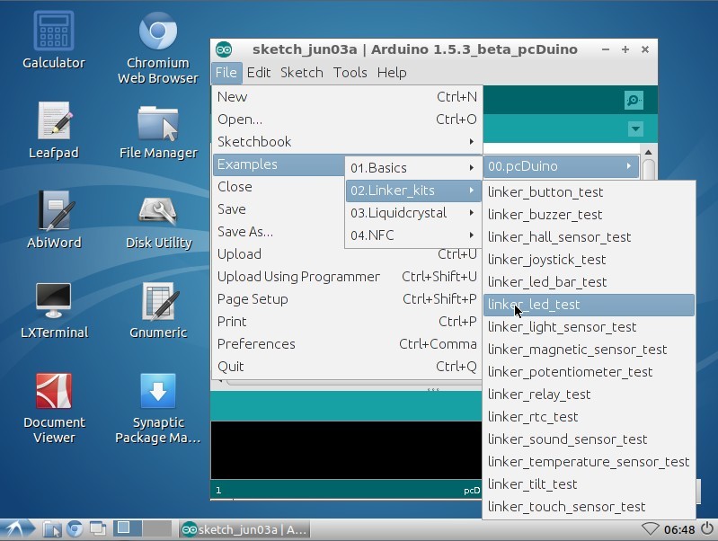
Now let’s look at one example. We will use Linker kit button module and Linker kit LED module to implement a simple function: when the button got pressed, and LED will turn on.
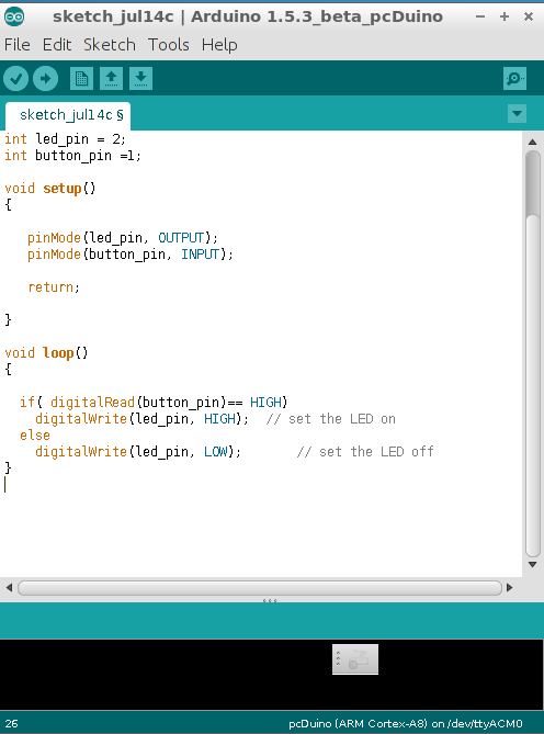
The code is shown below:
/*
* Linker kit button and LED test
*/
#include <core.h>
int led_pin = 2;
int button_pin =1;
void setup()
{
pinMode(led_pin, OUTPUT);
pinMode(button_pin, INPUT);
return;
}
void loop()
{
if( digitalRead(button_pin)== HIGH)
digitalWrite(led_pin, HIGH); // set the LED on
else
digitalWrite(led_pin, LOW); // set the LED off
}
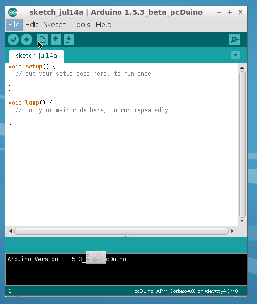
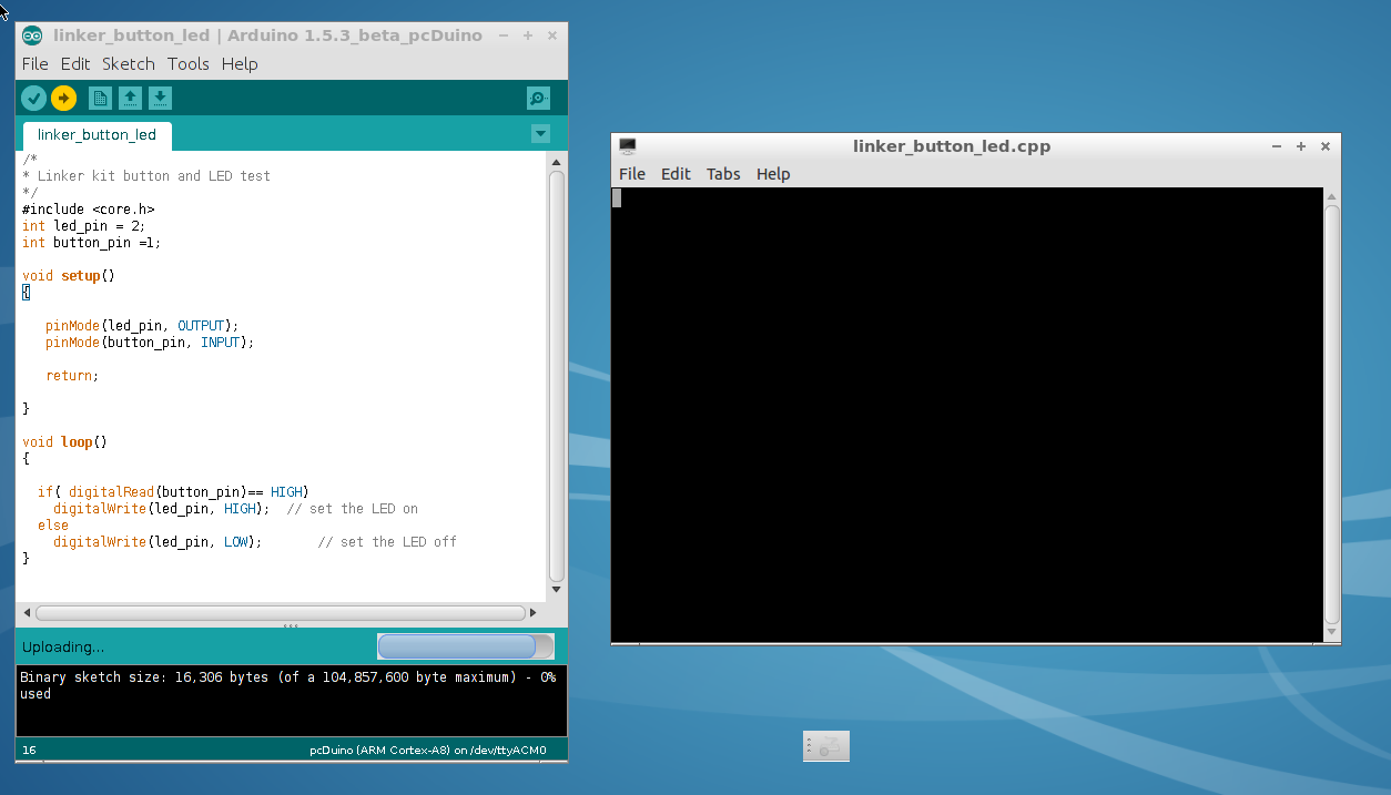
Launch the Arduino IDE for pcDuino, and click File->New.
Copy and paste the sample code into the new window:
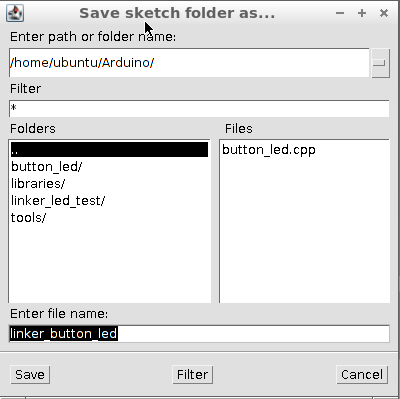
Save file as the following and name the file as linker_button_led.
Select the board type as pcDuino:
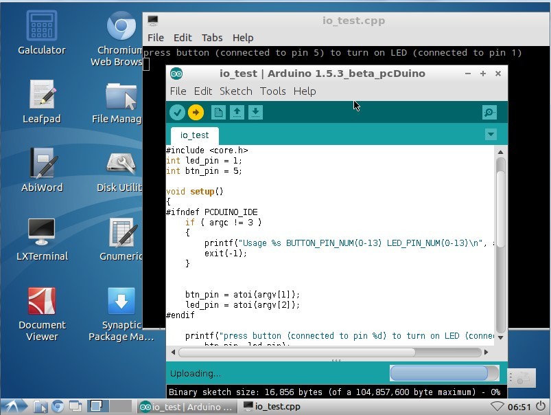
Click the upload button. A new window will pop up, and the code is running.
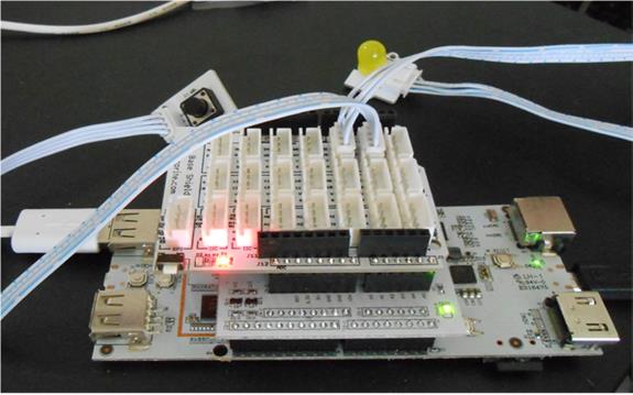
Hardware wise, the Linker button module is plugged to D1 and Linker LED module is plugged to D2. When the button is not pressed, the LED is off.
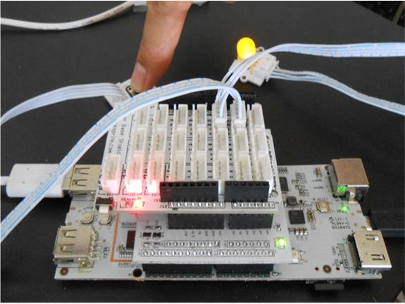
The LED will be on when the button is pressed.
 [/vc_column_text][/vc_tab][/vc_tour][/vc_column][/vc_row]
Leave a Reply
You must be logged in to post a comment.